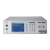
Electrical Safety Analyzer 19032-P Quick Start Guide
32
8. After GB CONTACT counting down for 3 seconds (Start Wait setting
time), then process test is the same as item 4 description.
4.7 Description of GB-Floating Board
4.7.1 Notice Items before Operating
1. Before turning on power, please peruse “Chapter 3 – Precaution
before Use” and remember it.
2. When turns on power, the analyzer will self-test. LCD shows “Find
GB-Float board”, it means the analyzer detected this function.
4.7.2 Description of GB-Floating Function
1. When the test mode is WAC, WDC or IR, capable of setting HV1
terminal on the rear panel is high voltage output terminal, grounding
terminal or Floating; HV2 terminal is grounding or Floating.
2. When the test mode is GB or LC
(option):
Drive- on rear panel connects with Drive- on front panel.
SENSE- on rear panel connects with SENSE- on front panel.
Drive+ on rear panel connects with Drive+ on front panel.
SENS+- on rear panel connects with SENSE+ on front panel.
3. The rear panel is equipped with another set of HV1 (Channel 3).
When the test mode is WAC, WDC or IR, capable of setting High, Low
terminal or Disable. When the test mode is LC
(option), HV1 on rear
panel only can be set as Low terminal or Disable.
i. When GFI setting is FLOAT under PRESET option, connection
diagram of front panel and rear panel terminal is as Figure 4-11
shown:

 Loading...