Electrical Safety Analyzer 19032-P Quick Start Guide
46
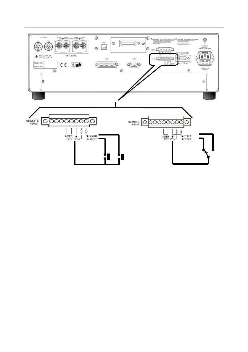
NO
Figure 4-19 Figure 4-20
2. As Figure 4-20, the main unit is under STOP status. NC point is
connecting to STOP and NO point connecting to START.
3. Some logical components such as transistor, FET, coupler. Also can
be used to connect as control circuit as Figure 4-21. The connecting
signal and circuit as Figure 4-21. Only the circuit includes the
following statuses, it can control the main unit.
(1) The signal voltage of HIGH should between 4.5 and 5V.
(2) The signal voltage of LOW should between 0 and 0.6V.
(3) The signal of LOW flowing current is 2mA or fewer.
(4) The action time of inputting signal should be over 20mS.

 Loading...

