Electrical Safety Analyzer 19032-P Quick Start Guide
I
2
I
C2
I
1
I
C1
47
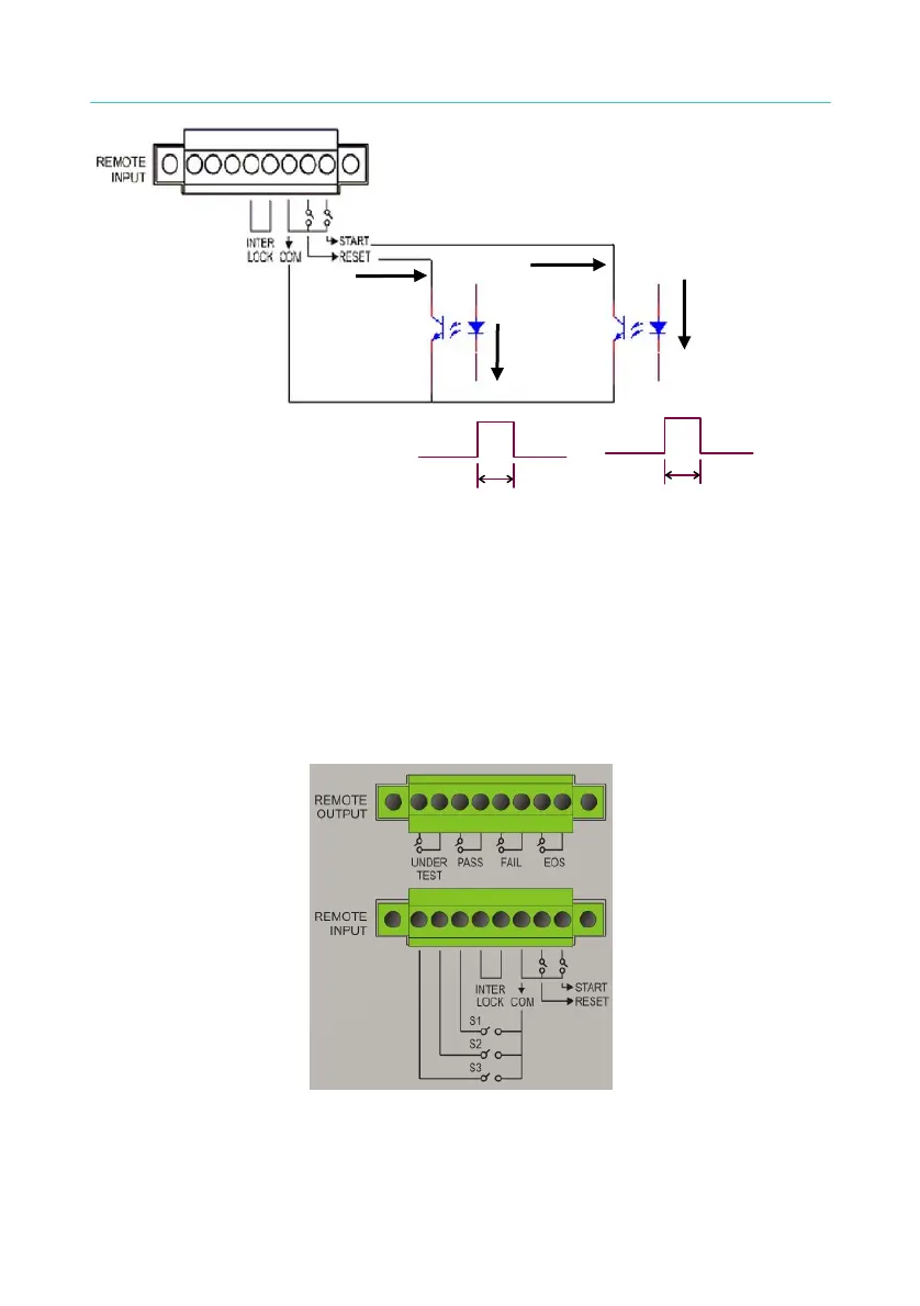
20mS or more
20mS or more
Figure 4-21
4. The relay switch control as Figure 4-19 and photo-coupler control as
Figure 4-21 are controlled by component contact. It is effective to
avoid error operation system which caused by interference. Although
the main unit has a lot of preventions, it is necessary to be careful that
interferences result from setting measurement system.
5. Pin diagram of REMOTE CONTROL as Figure 4-22. When users
desire to control by external, please remember this pin diagram.
Figure 4-22

 Loading...

