Operation and Setting
2-1
2. Operation and Setting
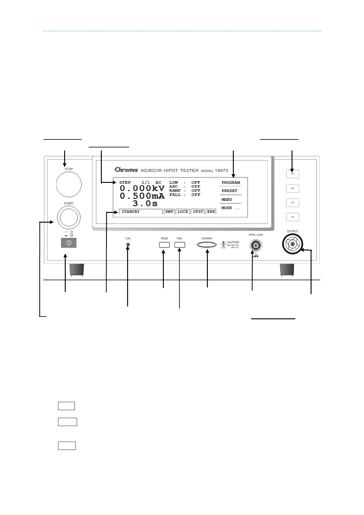
2.1 Front Panel
The front panel is divided into several function areas. This section explains each control and
the information displays on LCD.
Button Area Button Area
Stop Button Display Area Function Key Display Area Function Keys
Power Switch Status Line Pass Indicator Test Status Indicator Common Test Terminal
High Voltage Output Terminal
Start Button Calibration Switch Fail Indicator Terminal Area
2.1.1 Display Area
Function Key Display Area: Different function text appears in different menu. The
mapping function keys (F1-F4) are located at right. The function key is invalid if the text
is blank.
Status Line: This line shows the setting mode, value range, and test results.
RMT : When the text is highlighted, it means the system is under on-line status.
LOCK: When the text is highlighted, it means the system is under protection via
parameter.
OFST: When the text is highlighted, it means the leakage current has been offset by the
system.