Operation Overview
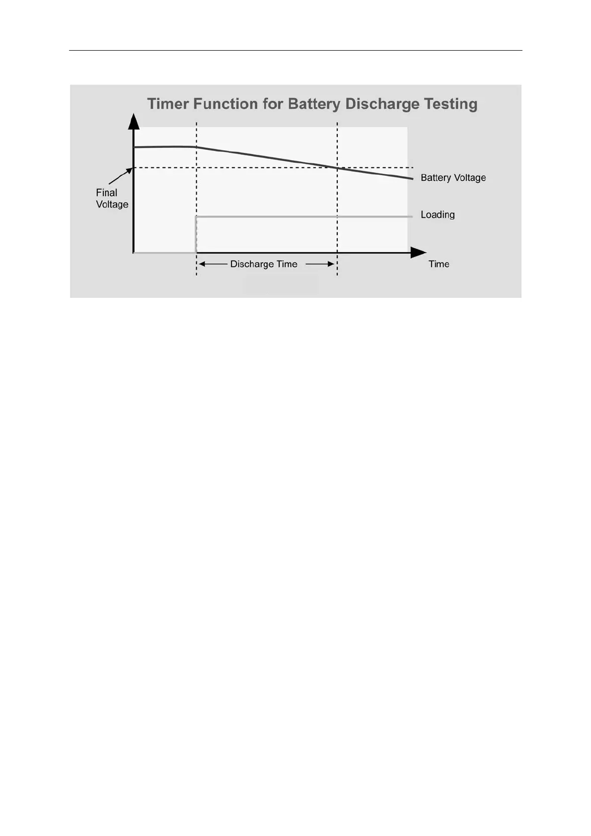
Figure 3-11
3.6 Measurements
The Load measures current, voltage, and power of the UUT and resistance of the Loading.
The sampling rate is about 8 mS. Voltage and current measurements are performed with a
15-bit resolution of full scale ratings.
There are three sets of 7-segment LEDs for the measuring data. One is for voltage, another is
for current, and the other is for Power or Resistance that you can select under the
configuration setting. The OHMS led will be on when you select the resistance
measurement.
3.7 Slew Rate & Minimum Transient Time
Slew rate is defined as the change in current over time. A programmable slew rate allows a
controlled transition from one load setting to another to minimize induced voltage drops on
inductive power wiring, or to control induced transients on a test device. If the transient
from one setting to another is large, the actual transient time can be calculated by dividing the
current transition by the slew rate. The actual transition time is defined as the time required
for the change of input from 10% to 90% or from 90% to 10% of the programmed excursion.
If the transition from one setting to another is small, the small signal bandwidth of Load will
limit the minimum transition time for all programmable slew rates. Because of the limit, the
actual transition time is longer than the expected time based on the slew rate. Therefore,
both minimum transition time and slew rate must be considered in the determination of actual
transition time. The minimum transition time is from 24 µS to 6 mS depending on the slew
rate setting.
3-11