EN7510364-00
EN - 12
4.7 Free-cooling
4.7.1 List of parameters
No.
PARAMETER NAME PARAMETER ADJUSTMENT
Description Display conditions Adjustment possible By default
A111 FREE COOLING OPERATION
A10 = NO
A02 = (1 or Yes) and
A03 = 1 LT water circuit
YES or NO NO
A112 SELECTION EXT. TEMP. A111 = Yes 5 to 20 in increments of 1 10
A117 MIN DIFFERENCE FOR FREECOOLING
DEACTIVATION
A111 = YES
0.5°C to 15°C in increments
of 0.5
2
A118
MAX DIFFERENCE FOR
FREECOOLING ACTIVATION
A111 = YES
1°C to 10°C in increments
of 0.5
4
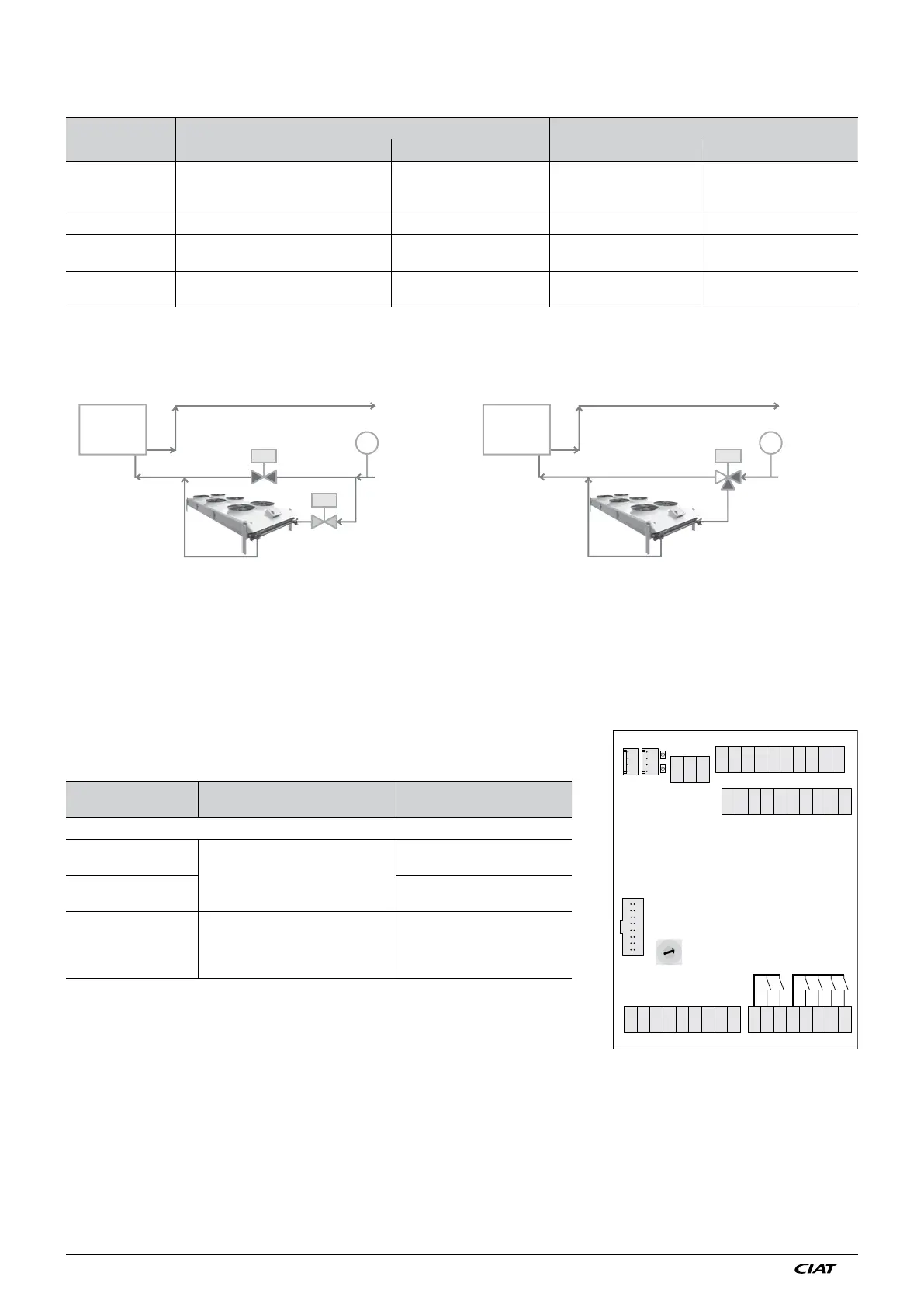
4.7.2 Schematic diagram
Depending on the difference between the return operating temperature and the outdoor air freecooling operation is authorised
(or not). If the value of the difference is less than A117 freecooling operation is stopped and when the value is greater than A118
operation of the drycooler is authorised.
In free cooling operation, priority of operation is given to the drycooler. The drycooler controls the control stages according to the
control setpoint and the fluid temperature. When the drycooler is at 100% power it will send control authorisation to the water
chiller. The water chiller controls according to its own parameters. This authorisation is timed for 15 minutes when the drycooler
is started.
4.7.3 Electrical connections
● ADD2 board
Rotary switch RC1 in position 2
CONNECTOR/
TERMINALS
DESIGNATION DIRECTION OF ACTIO
On/Off outputs
J3 terminals 1-2
Water chiller in free cooling mode
Provision of 2 dry contacts with direction
of action reversed.
The contact closes to allow the
operation of the water chiller.
J3 terminals 1-3
(From V13)
The contact opens to allow the
operation of the water chiller.
J3 terminals 4-5-6
Free cooling valve control
Terminal 4: voltage 230V 50Hz
Terminal 5: Fluid towards the chiller
Terminal 6: Fluid towards the drycooler
See wiring diagram
Note:
For CIAT water chillers, do not connect J3 1-2; instead, use
the bus connection (J10 water chiller board/J9 drycooler board)
J2
J5
J6
J4
J8
J7
RC1
J3
J1
++
0
1
2
3
4
5
6
7
8
9
54321
321
1234
1234
45678123567891234
5432110 9876
10 9876
15 14 13 12 1120 19 18 17 16
2468101214
16
13579111315
Assembly with two 2-way valves
TT
V1
V2
WATER
CHILLER
Sensor
Return
operating
temperature
Assembly with two 3-way valves
Sensor
Return
operating
temperature
WATER
CHILLER
TT
V1