EN
EN - 17
EN7510364-00
+
TR1
SP1
PL1
J4J2 J3
J6J8
J5J7
J9J11 J10
W3
J14J12J13
D46 D48D50 D52
12 11 10 987654321
12345678910111213141516
11 10 987654321
12 11 10 987654321 11 10 987654321321321 321
43214 321
8642
7531
112345 123
+++
Shared
Shared
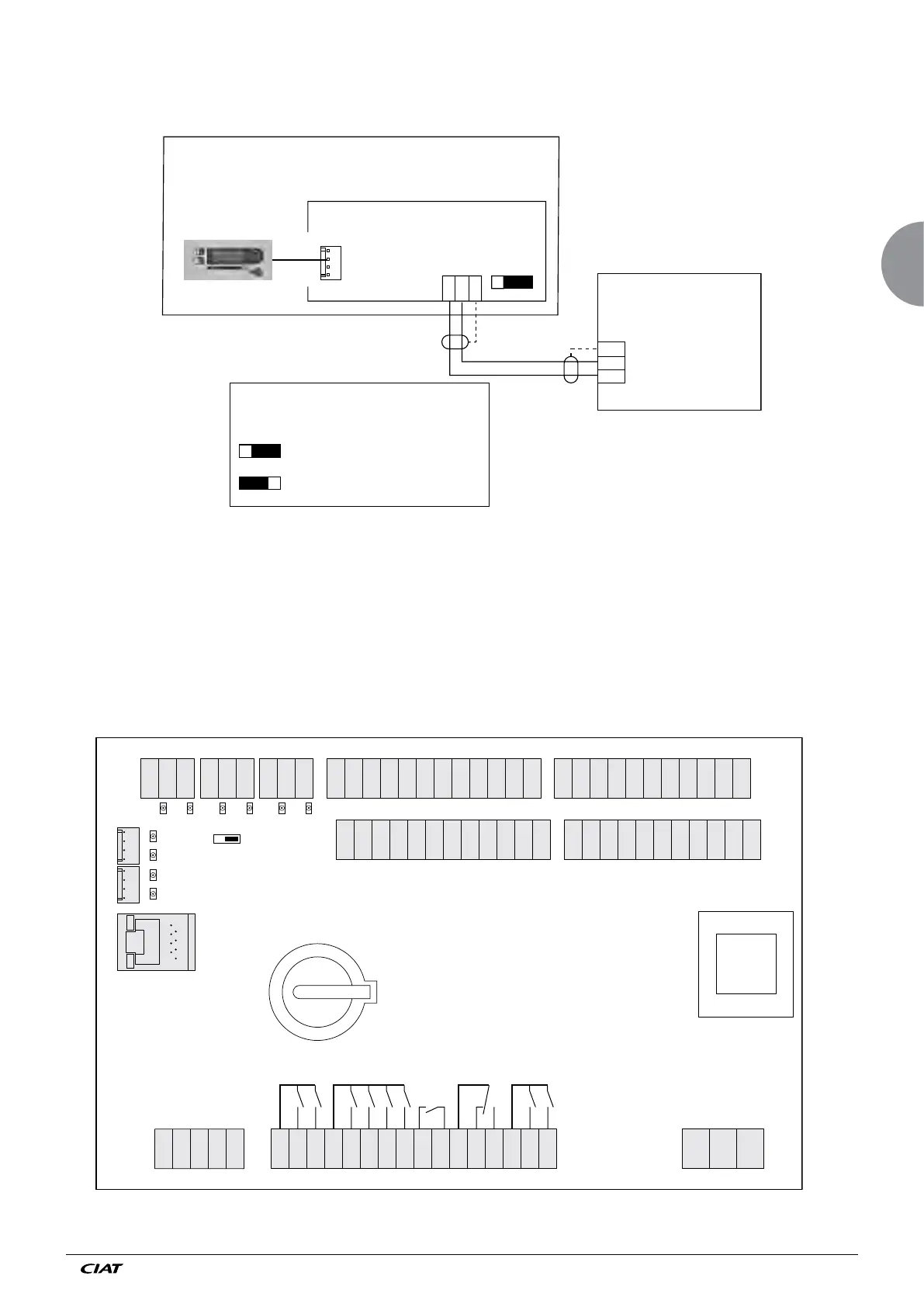
6.2 Board connections
6.2.1 Motherboard
The structure of the motherboard is illustrated in the diagram below:
1234
123
J9
J12
W3
3
2
1
DRYCOOLER
Local console
board
BOARD
J10
B (-)
A (+)
Position of line termination
resistance switch W3
OFF ON Position W3 if drycooler is the last
unit in link
Position W3 if drycooler is not the
last unit in link
Water chiller
6.1.3 Link with a CIAT chiller