EN7510364-00
EN - 18
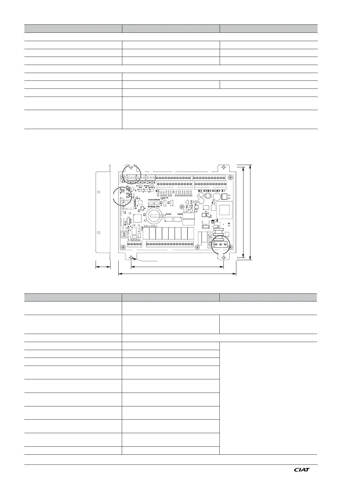
6.2.2 Relay motherboard
To be installed by the customer in its main electrical cabinet
16025
156
203.4
164
Ø 4.5
J2 J3
J1
J14
J15
J4
J12
J13
J6J8
J2 J3
J1
J15
J4
J13
J6J8
J5
J7J11 J9 J5J7J11
J9
C
J10
J10
B
J14
J12
CONNECTOR/TERMINALS DESIGNATION DIRECTION OF ACTION
On/Off inputs
J6 terminals 1-3 Fan manual override The fans turn on when the contact closes
J6 terms. 2-3 Automatic operation control The machine stops when the contact opens
J6 terminals 4-6 Setpoint 1/Setpoint 2 selection Setpoint 2 is enabled when the contact is closed.
Analogue Inputs
J7 terminals 1-2 Outdoor temperature sensor
J9 terminals 1-2-3 BUS feed connection to J10 of the water chiller board
J10 terminals 1-2-3 BUS power supply connected by shielded cable to J1 on relay board or J1 on remote control console. (terminal 1
to terminal 1, terminal 2 to terminal 2 and shielding to terminals 3).
J11 terminals 1-2-3 BUS power supply connected by shielded cable to J9 on the CONNECT2 board or J12 on the CONNECT
board or JA11 on the XTRACONNECT board. (terminal 1 to terminal 1, terminal 2 to terminal 2 and shielding to
terminals 3) or customer CMS.
Its potential-free (dry) contacts allow the following information to be viewed remotely:
CONNECTOR/TERMINALS DESIGNATION DIRECTION OF ACTION
J11 terminals 1-2-3
BUS feed connected by shielded cable to the unit's control board. (Terminal 1 to terminal 1, terminal 2 to terminal
2 and shielding to terminals 3).
J4 terminals 1-2-3 Single-phase 230 V power supply. (L - N T)
Terminal 1 Neutral
Terminal 2 Phase
Terminal 3 Earth
J13 terminals 1-2-3 If ADD3 board, terminal J1 connected to ADD3 board (30 cm of cable supplied with the ADD3 board)
J3 terminals 1-2 Unit running
The contacts are closed when the unit is running
without any faults.
J3 terminals 1-3 Sensor fault, coil 1, circuit 1
J3 terminals 4-5 Sensor fault, coil 2, circuit 1
J3 terminals 4-6 Fan fault, stage 1/fan
fault, stage 1, line 1
J3 terminals 4-7 Fan fault, stage 2/fan
fault stage 2, line 1
J3 terminals 4-8 Fan fault, stage 3/fan
fault stage 3, line 1
J3 terminals 9-10 Fan fault, stage 4/fan
fault stage 4, line 1
J3 terminals 11-13 Fan fault, stage 5/fan
fault stage 5, line 1
J3 terminals 14-15 Fan fault, stage 6/fan
fault stage 6, line 1
J3 terminals 14-16 Sensor fault, coil 1, circuit 2