EN
EN - 19
EN7510364-00
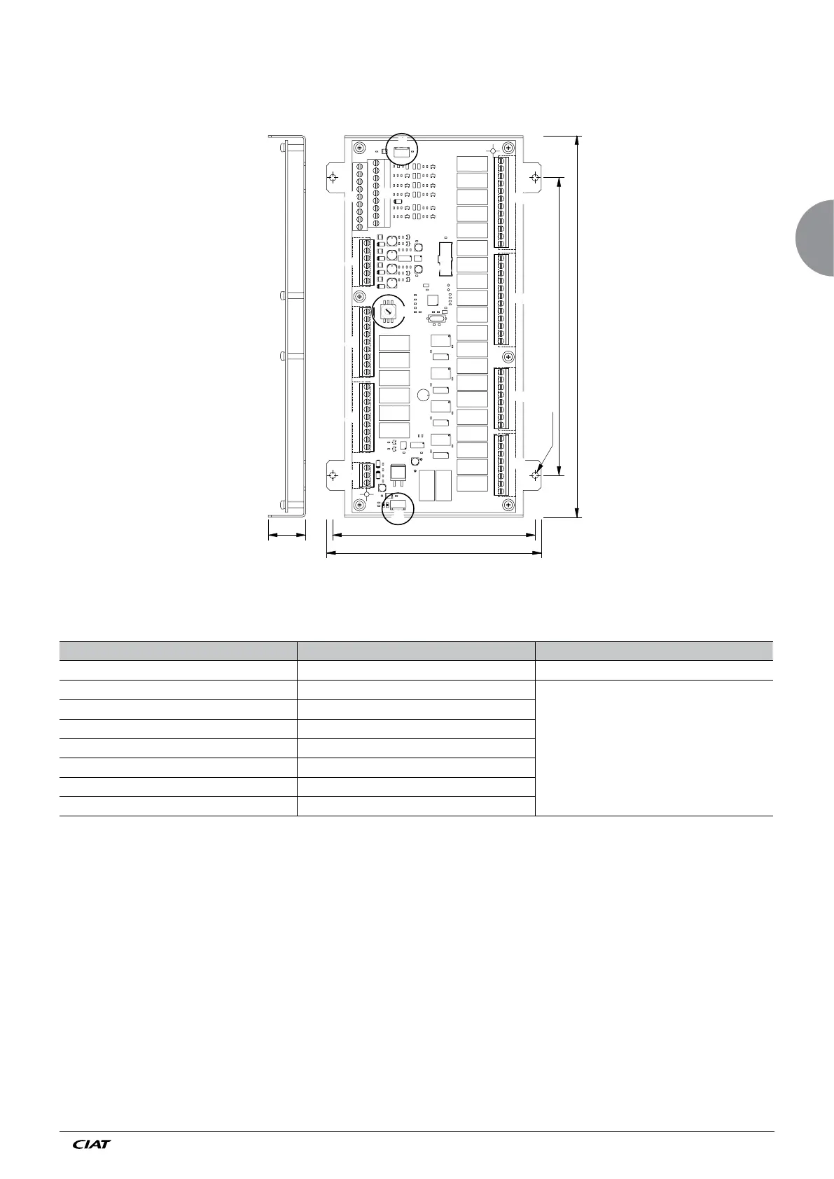
Its potential-free (dry) contacts allow the following information to be viewed remotely:
CONNECTOR/TERMINALS DESIGNATION DIRECTION OF ACTION
J1 Relay board block J13
J9 terminals 1-2 Sensor fault, coil 2, circuit 2
The contacts are closed when the unit is running
without any faults.
J9 terminals 1-3 Fan fault, stage 1, line 2
J9 terms. 1-4 Fan fault, stage 2, line 2
J9 terms. 5-6 Fan fault, stage 3, line 2
J9 terms. 5-7 Fan fault, stage 4, line 2
J9 terms. 5-8 Fan fault, stage 5, line 2
J10 terminals 1-2 Fan fault, stage 6, line 2
J9
136
Ø 4.5
200
25
J12
J11
J10
J12
J11
J9
J10
J7
J3
J5
J6
J3
J5
J7
J6
256.4
144
J4J4
J2
J2
J8
J8
J1
J1
J13
J13
0
1
2
3
4
5
6
7
8
9
D
ADD3 additional relay board (2 refrig. circuits)
To be installed on the main board by the customer.
Board delivered with a 30 cm connecting cable