Water chillers and
air-water heat pumps
HEAT PUMPS - AIR CONDITIONING - REFRIGERATION - AIR HANDLING - HEAT EXCHANGE - NA 12.122 H
12
CIATCooler LP
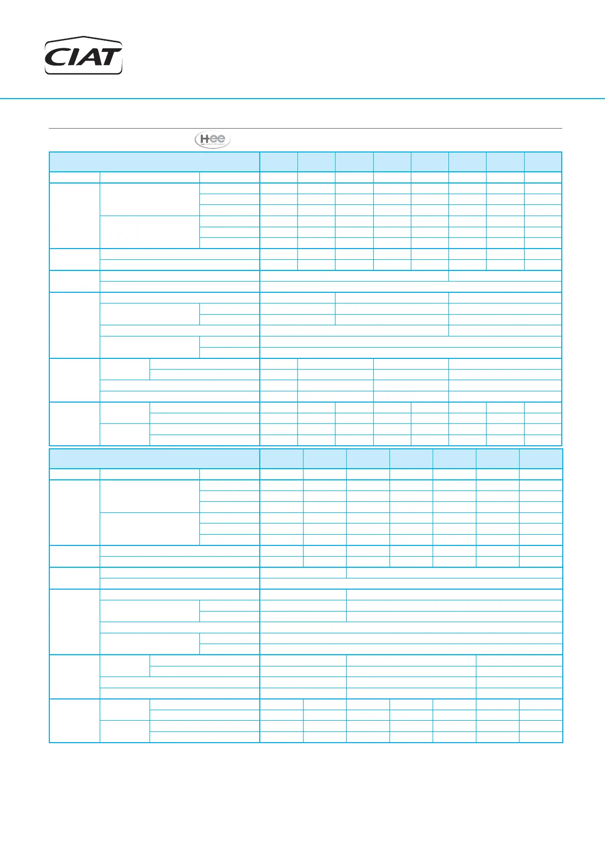
4. TECHNICAL CHARACTERISTICS
HEE version with pump included
CIATCooler LPC / ILPC
90V-
HEE
100V-
HEE
120V-
HEE
160V-
HEE
180V-
HEE
200V-
HEE
240V-
HEE
280V-
HEE
Cooling
Seasonal effi ciency
ESEER 2,95 3,00 3,22 3,17 3,02 3,39 3,44 3,15
Heating
Seasonal effi ciency
Average climate
SCOP 3,12 2,95 3,33 3,20 3,08 3,34 3,24 3,08
ŋs Heat 122% 115% 130% 125% 120% 131% 126% 120%
Prated (kW) 15,75 17,51 21,70 26,39 30,36 34,52 45,31 52,33
Seasonal effi ciency
Warmer climate
SCOP 3,64 3,56 3,77 3,67 3,60 3,77 3,76 3,54
ŋs Heat 143% 139% 148% 144% 141% 148% 147% 139%
Prated (kW) 13,12 14,69 18,05 22,40 25,83 29,71 34,73 38,82
Indoor
circuit
Nominal water fl ow (m
3
/h) 3,2 3,7 4,5 5,4 6,2 7,4 9,3 10,2
Pressure drop (m.w.c.) 2,3 3,1 2,5 3,5 4,6 3,1 2,2 2,6
Expansion
vessel
Volume (l) 12 20
Filled pressure (kg/cm
2
) 1,5
Buffer tank
(LPC / ILPC
+ module)
Volume of the buffer tank (l) 100 150 225
Maximum water capacity
of the installation
Water 40ºC (l)
700 650 1100
Water 50ºC (l)
410 360 625
Drained diameter 3/4” M 1” M
Anti-freeze elec. heater
(standard)
Voltage 230 V / I ph
Output (kW) 1 (4,3A)
Dimensions
Length (mm)
LPC / ILPC 1117 1398 2113 2673
Module 1000 1000 1000 1000
Width (mm) 860 860 860 860
Height (mm) 1447 1727 1447 1727
Weight
LPC / ILPC
Empty (kg) 310 370 386 469 476 654 678 686
In operation (kg) 327 390 408 497 503 690 717 724
Hydraulic
module
Empty (kg) 138 151 161 154 154 169 169 169
In operation (kg) 242 256 315 307 310 404 404 404
CIATCooler LPC / ILPC
320V-
HEE
360V-
HEE
420V-
HEE
480V-
HEE
600V-
HEE
640V-
HEE
720V-
HEE
Cooling
Seasonal effi ciency
ESEER 3,19 3,20 3,40 3,30 3,24 3,30 3,27
Heating
Seasonal effi ciency
Average climate
SCOP 3,19 3,09 2,96 3,36 3,24 3,11 3,05
ŋs Heat 124% 120% 115% 132% 126% 121% 119%
Prated (kW) 55,66 63,89 74,33 97,30 99,47 112,13 128,57
Seasonal effi ciency
Warmer climate
SCOP 3,73 3,54 3,54 3,35 3,35 3,62 3,67
ŋs Heat 146% 139% 139% 131% 131% 142% 144%
Prated (kW) 46,66 51,61 60,07 73,24 80,05 91,09 103,23
Indoor
circuit
Nominal water fl ow (m
3
/h) 11,7 13,3 15,6 17,2 21,0 23,2 26,5
Pressure drop (m.w.c.) 5,0 6,2 9,3 11,3 11,4 10,3 13,6
Expansion
vessel
Volume (l) 35 50
Filled pressure (kg/cm
2
) 1,5
Buffer tank
(LPC / ILPC
+ module)
Volume of the buffer tank (l) 225 275
Maximum water capacity
of the installation
Water 40ºC (l)
2100 3035
Water 50ºC (l)
1260 1840
Drained diameter 1” M
Anti-freeze elec. heater
(standard)
Voltage 230 V / I ph
Output (kW) 1 kW (4,3 A)
Dimensions
Length (mm)
LPC / ILPC 3400 3600 4500
Module 1000 1000 1000
Width (mm) 900 1150 1200
Height (mm) 1970 1970 1970
Weight
LPC / ILPC
Empty (kg) 979 985 1324 1400 1481 1782 1793
In operation (kg) 1028 1034 1391 1467 1550 1863 1875
Hydraulic
module
Empty (kg) 193 193 225 225 225 236 236
In operation (kg) 424 424 508 508 508 523 523
European Seasonal Energy Effi ciency Ratio (ESEER) obtained in accordance with the calculation conditions established by the certifi cation body EUROVENT.
Values calculated in accordance with the EN-14825-2013 standard given for bivalente temperature of -5ºC in average climate and 2ºC in warmer climate.
The water capacity for the installation indicated in this table corresponds to the maximum that the installation allows based on the expansion vessel assembled on the unit.
The volume of the buffer tank has been taken into account for this section. In case the capacity of the installation is greater, it is necessary to add a supplementary expansion
vessel to the installation based on its volume.
This temperature corresponds to the temperature that the circuit may reach when the unit is stopped. This case must be considered for cooling-only units.
This temperature corresponds to the maximum temperature that the circuit may reach when operating in a heat pump.
Minimum distance between the unit and the separate hydraulic module: 167mm. In models 640 and 720: 187mm.