HEAT PUMPS - AIR CONDITIONING - REFRIGERATION - AIR HANDLING - HEAT EXCHANGE - NA 12.122 H
Water chillers and
air-water heat pumps
37
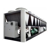
CIATCooler LP
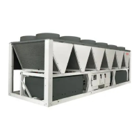
Protective grille
Coil protection grille
The CIATCooler units can
include a protection grille for
the coil. This grille is fi xed by
modules in the holes made
for this purpose in the unit
supports.
Separate
module
Ø connections
on module side
Ø connections
on unit side
90V-STD to 100V-STD
90V-HEE to 100V-HEE
1 1/4” M 1 1/4” H
120V-STD to 180V-STD
120V-HEE to 180V-HEE
1 1/2” M 1 1/2” H
200V-STD to 600V-STD
200V-HEE to 360V-HEE
2” M 2” H
640V-STD to 960V-STD
420V-HEE to 720V-HEE
2 1/2” M 2 1/2” H
Minimum distance between the unit and the separate module:
167mm. In models 640V-720V-HEE: 187mm.
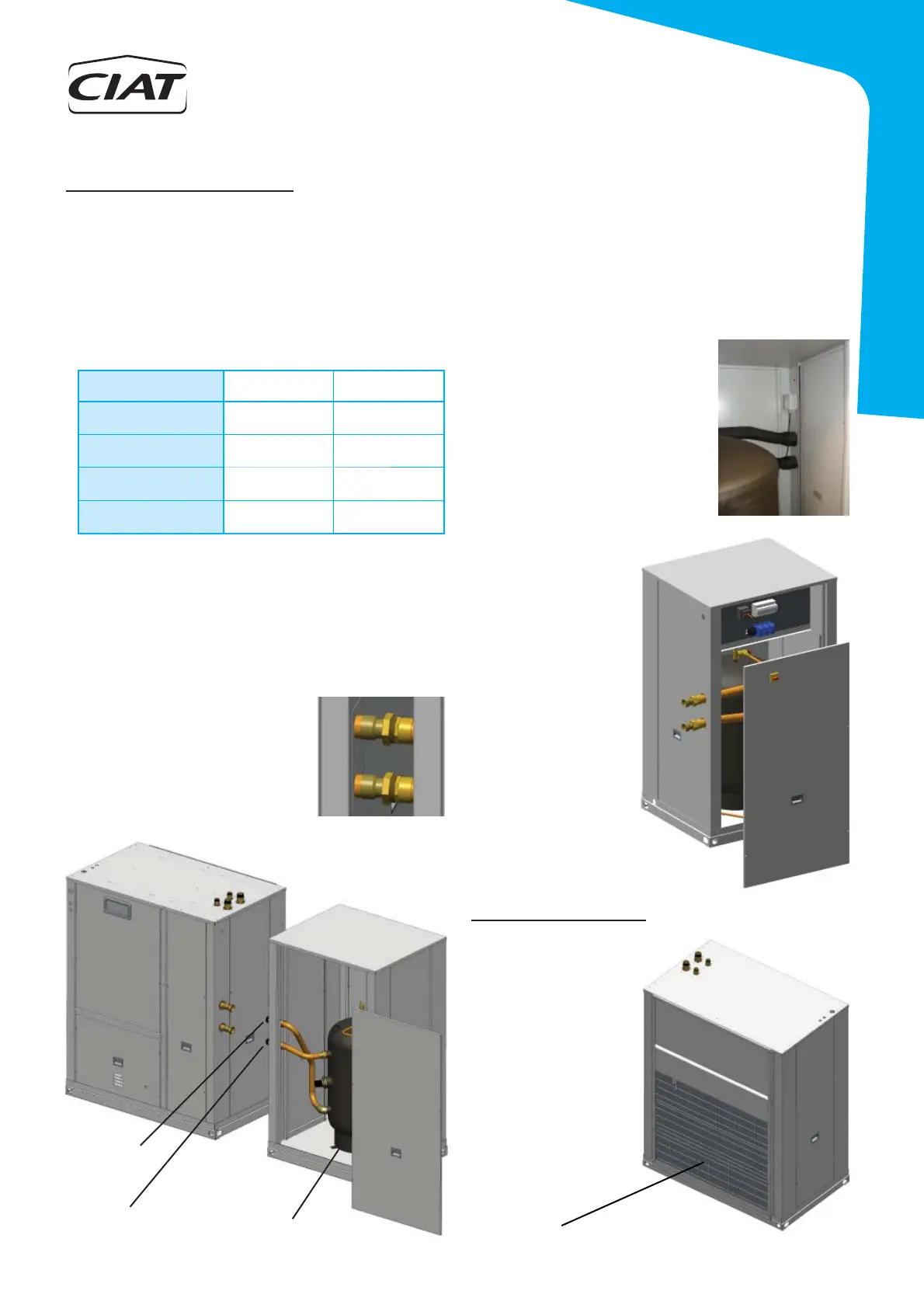
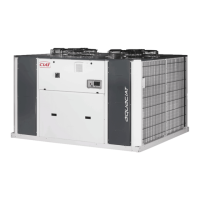
Separate hydraulic module
A hydraulic module can be coupled to units with LPC / ILPC version.
This one includes a thermal buffer tank made of black stainless steel,
painted, and thermally insulated.
The module can be supplied:
- Coupled to the LPC / ILPC unit, models 90 to 360 (STD version) and
90 to 280 (HEE version).
- Separate for connection on site by the installer. The diameters of the
hydraulic connections between the unit and the module are:
In this case, the fl exible connections of 500 mm are recommended
(option).
Note: In order that the unit with hydraulic module could incorporate
the option of antifreeze protection with fl exible electric heaters on the
hydraulic circuit piping, the module must be coupled to the unit, or in
the case of separate, do not add additional
elements in the threaded connections
between module and unit, and isolate
these connections.
Therefore, antifreeze protection on piping
is not compatible with fl exible hydraulic
connections.
LPC / ILPC
Hydraulic module
Buffer tank
Water inlet
to the tank
Water outlet
from the tank
The buffer tank includes an anti-freeze electrical heater (1kW).
Optionally, in heat pump units, this heater can be replaced by a support
heater in 1 to 4 stages.
With separate hydraulic module, the installer must perform the wiring
from this module to the electric panel of the machine.
* 1 power stage: the terminal block for
connecting the electrical heater to the unit
are located in a box inside the module,
on the same pillar that the hydraulic
connections.
- Anti-freeze electrical heater (1 kW):
230V / I ph 2-wire + ground
- Support electrical heater (3 to 12 kW):
400 V / III ph 3-wire + ground
Wiring of the buffer electric support
* 2 to 4 power stage (24
to 48 kW): the module
incorporates an auxiliary
electric panel, 3-wire
power supply (door switch)
+ ground + 6 to 8-wire (2
to 4 stages) in a terminal
block for connection of
electrical heaters (see
wiring diagram).