Water chillers and
air-water heat pumps
HEAT PUMPS - AIR CONDITIONING - REFRIGERATION - AIR HANDLING - HEAT EXCHANGE - NA 12.122 H
38
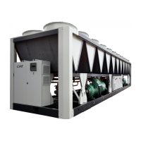
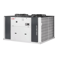
CIATCooler LP
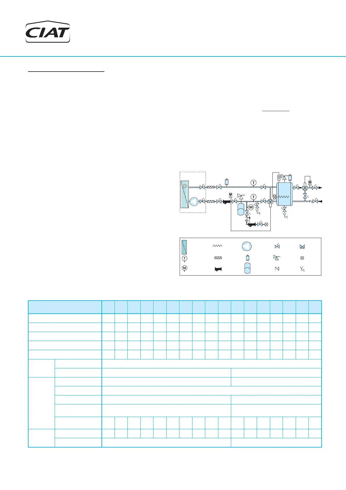
Cooling recovery circuit
The system consists in a hot water supplying by an heat recovery
system on the compressor(s) discharge gas, on an auxiliary
desuperheater exchanger.
On an heat pump model, the optional desuperheater can be used
whatever the running mode, COOLING or HEATING.
This optional equipment is only available on request, and factory
mounted.
Operating mode
The heat recovery is possible only if the unit is running, on COOLING
mode or on HEAT PUMP mode.
For the same cooling or heating capacity, the desuperheater system
allows a free heating of hot water with a reduction of the total input
power of the unit.
Principle and precaution of hydraulic connection
In order to allow the unit to start up and to run under good conditions,
the circuit must be as short as possible, and the water fl ow of the
desuperheater must start slowly to normal operating condition, with a
water fl ow equal to 10% of its standard value, and must be calculated
for a hot water inlet temperature of +50°C.
Thus, it is recommended to have a hydraulic diagram making it possible
to obtain very quickly a hot water at the inlet of the desuperheater (3 ways
valve + controller + temperature sensor on the exchanger water inlet).
The controller set point must be adjusted to +50°C minimum.
The recovery circuit must be done in accordance with the standards
in force and plan all of the necessary elements in a closed circuit:
circulation pump (optionally supplied), expansion vessel, safety valve,
mesh fi lter, fi ller, drainer, bleeders, thermometers, pressure gauges and
cut-off and insulation valves.
The circulation pump can only work in a closed circuit. The command
is performed from a thermostat located on the unit.
Attention: a detailed attention must carried with the selection of the
expansion tank, because the recovery water circuit can reach the
temperature of 120°C in the event of stopping of the circulator or non
hot water consumption.
- Install heating elements on all pipes that could be exposed to freezing
temperatures.
PLATES
EXCHARGER
EXPANSION
VESSEL
ELECTRICAL
HEATER
MESH
FILTER
VA
SHUT-OFF
LVE
DRAINAGE
CIRCUIT
SAFETY
VALVE
NO RETURN-
VALVE
VA
AIR BLEEDER
LVE
THERMOMETER
MANOMETER
CIRCULATOR
PUMP
FILLED
CIRCUIT
3-WAY
VALVE
FLEXIBLE
CONNECTION
Agua de red
A consumo
Opcional
CIATCooler
Min. 50ºC
Technical characteristics of the recovery circuit with the STD version
Capacity recovered by the desuperheater circuit for nominal conditions and recovery water at 50/60ºC.
Models 90 to 360, the change of speed of the pump is made by a button that changes color according to the selected speed (blue: low; green: medium; yellow: high).
CIATCooler
90V-
STD
100V-
STD
120V-
STD
160V-
STD
180V-
STD
200V-
STD
240V-
STD
280V-
STD
320V-
STD
360V-
STD
420V-
STD
480V-
STD
600V-
STD
640V-
STD
720V-
STD
840V-
STD
960V-
STD
Recovery capacity (kW)
4,4 5,2 6,2 8,1 8,9 10,8 12,2 13,8 16,8 18,3 21,9 23,9 29,4 33,2 37,7 43,9 47,5
Nominal water fl ow (m
3
/h) 0,38 0,45 0,53 0,70 0,76 0,93 1,05 1,18 1,44 1,58 1,88 2,06 2,53 2,85 3,24 3,77 4,08
Pressure drop (m.w.c.) 0,06 0,09 0,17 0,30 0,36 0,53 0,67 0,32 0,48 0,57 1,15 1,38 2,08 1,33 2,31 3,13 3,74
Cooling capacity (kW) 17,8 21,3 25,3 33,0 36,2 44,0 49,6 56,1 68,3 74,6 89,3 97,6 119,7 135,2 153,1 178,2 194,5
Power input (kW) 6,8 7,9 8,6 10,8 12,7 15,6 17,0 19,5 21,7 25,5 28,1 32,2 42,3 40,5 49,9 56,0 65,3
Hydraulic
connections
Type Threaded
Diameter 1” M 1 1/4” H
Pump
(optional)
Type Humid rotor Dry rotor
Number 1
Motor output (kW) 0,05 0,25
Maximum absorbed
current (A)
0,4 2,0
Avail. pressure (m.w.c.)
(max. pump speed)
5,54 5,45 5,35 5,15 5,07 4,85 4,69 4,49 4,11 3,90 11,18 11,03 10,61 10,32 9,47 8,88 8,47
Additional
weight
Recovery circuit (kg) 5,3 5,3 6,8 6,8 6,8 10,7 11,6 11,6 11,6 11,6 21,9 22,0 21,9 57,7 56,1 59,4 59,6
Pump (optional) (kg) 3,2 14,6