HEAT PUMPS - AIR CONDITIONING - REFRIGERATION - AIR HANDLING - HEAT EXCHANGE - NA 12.122 H
Water chillers and
air-water heat pumps
27
CIATCooler LP
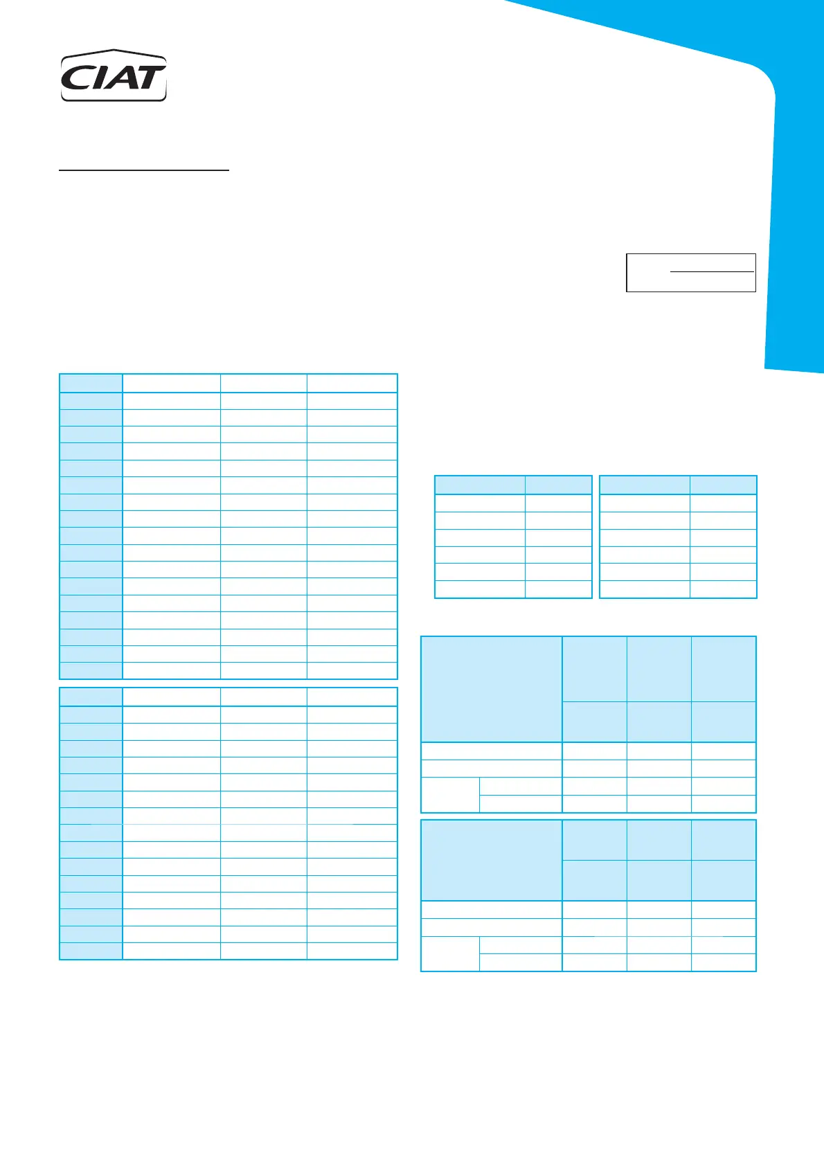
Minimum installation volume
The electronic control for these units incorporates an auto-adaptive
control for the compressor operating time based on the time set for
anti-short-cycle.
This control reduces the number of times the compressor is started
up and permanently adjusts the system's thermal inertia, favouring
the reduction of the minimum volume of water in the installation. The
size of the buffer tank can also be decreased since the unit will be
stopped for less time.
Where:
V
inst
Installation volume (l)
V
inst
Expansion vessel volume (l)
V
1
Initial volume of 1kg of water (at water temperature with the machine stopped)
V
2
Final volume of 1kg of water (at water temp. with the machine at normal speed)
P
f
Final network pressure (safety valve pressure in bars + 1)
P
i
Initial network pressure (absolute fi lling pressure of the installation in bars)
Note: If the hydraulic circuit has a buffer tank, its volume must be taken
into account for this calculation.
• Volume occupied by 1kg of water at different temperatures:
Maximum installation volume
The water capacity for the installation obtained from this equation
corresponds to the maximum that
the installation allows based on the
expansion vessel assembled.
Installation water volume
Temperature (ºC) Volume (l) Temperature (ºC) Volume (l)
0 1,00013 50 1,0121
4 1,00000 60 1,0171
10 1,00027 70 1,0227
20 1,00177 80 1,0290
30 1,00435 90 1,0359
40 1,00782 100 1,0434
f
ifvessel
INST
PVV
PPV
V
⋅−
−
⋅
)(
)(
12
=
The calculation of the minimum water volume has been done for nominal
EUROVENT conditions, only in cooling mode. This value is applicable
for the majority of refrigeration applications (group with fan-coil units).
Note: The buffer tank is indispensable in installations that operate with a
reduced volume of water (group with an air handling unit) or for industrial
processes. For applications with a heat pump, it is recommended that
the buffer tank be used in order to maintain a stable temperature during
the defrosting cycles.
The water capacity for the installation indicated in this table corresponds
to the maximum that the installation allows based on the expansion vessel
assembled on the unit. The volume of the buffer tank has been taken into
account for this section. In case the capacity of the installation is greater,
it is necessary to add a supplementary expansion vessel to the installation
based on its volume.
This temperature corresponds to the temperature that the circuit may reach
when the unit is stopped. This case must be considered for cooling-only units.
This temperature corresponds to the maximum temperature that the circuit
may reach when operating in a heat pump.
Maximum volume of water in an installation with a hydraulic module:
Hydraulic connections
CIATCooler
Minimum volume (I) Minimum fl ow (l) Maximum fl ow (l)
90V-STD
101 2,2 6,2
100V-STD
120 2,7 7,4
120V-STD
143 3,1 8,8
160V-STD
187 4,1 11,3
180V-STD
204 4,3 12,7
200V-STD
123 4,7 15,0
240V-STD
138 6,2 17,2
280V-STD
156 7,2 19,2
320V-STD
189 8,3 23,6
360V-STD
207 8,6 26,0
420V-STD
248 12,2 31,4
480V-STD
271 13,4 34,5
600V-STD
333 16,9 42,1
640V-STD
185 18,2 48,2
720V-STD
210 20,9 54,3
840V-STD
244 24,1 63,5
960V-STD
265 26,6 69,4
CIATCooler
Minimum volume (I) Minimum fl ow (l) Maximum fl ow (l)
90V-HEE
107 2,8 6,7
100V-HEE
132 2,9 8,1
120V-HEE
152 3,8 9,5
160V-HEE
189 3,7 11,7
180V-HEE
210 4,0 12,8
200V-HEE
129 5,7 16,2
240V-HEE
152 6,5 19,3
280V-HEE
172 7,6 21,4
320V-HEE
187 9,1 23,6
360V-HEE
214 10,7 26,8
420V-HEE
251 12,2 31,7
480V-HEE
278 13,5 34,9
600V-HEE
344 17,4 42,8
640V-HEE
183 18,1 47,5
720V-HEE
211 21,2 54,3
LPC + module
90V-STD
100V-STD
120V-STD
160V-STD
180V-STD
200V-STD
240V-STD
280V-STD
320V-STD
360V-STD
90V-HEE
100V-HEE
120V-HEE
160V-HEE
180V-HEE
200V-HEE
240V-HEE
280V-HEE
Expansion vessel (l)
12 12 20
Buffer tank (I)
100 150 225
Max.
volume
Water 40ºC (l)
700 650 1100
Water 50ºC (l)
410 360 625
LPC + module
420V-STD
480V-STD
600V-STD
640V-STD
720V-STD
840V-STD
960V-STD
320V-HEE
360V-HEE
420V-HEE
480V-HEE
600V-HEE
640V-HEE
720V-HEE
Expansion vessel (l)
35 50 50
Buffer tank (I)
275 275 375
Max.
volume
Water 40ºC (l)
2050 3035 2985
Water 50ºC (l)
1210 1840 1790