Water chillers and
air-water heat pumps
HEAT PUMPS - AIR CONDITIONING - REFRIGERATION - AIR HANDLING - HEAT EXCHANGE - NA 12.122 H
24
CIATCooler LP
Connection of remote-controlled functions
Attention: With low outdoor temperatures, the electrical heater-based
anti-freeze protection option for the pan is recommended. Mandatory
when outdoor temperatures are below 3°C.
Condensate drain connection
- In LP / LPC units, the condensate drain pan includes a a bronze,
bleeding trunk for draining condensates.
• Mod. 90 to 360 (STD version) & 90 to 280 (HEE version): 3/4” M
• Mod. 420 to 960 (STD version) & 320 to 720 (HEE version): 1 1/4” M
- The optional hydraulic module for LPC units, incorporates a bronze,
bleeding trunk for draining from the buffer tank.
• Mod. 90 to 180 (STD version) & 90 to 180 (HEE version): 3/4” M
• Mod. 200 to 960 (STD version) & 200 to 720 (HEE version): 1” M
- Models in which the module can be sent coupled to the unit, this
will be the only bleeding trunk for draining condensates and draining
from the buffer tank.
• Mod. 90 to 180 (STD version) & 90 to 180 (HEE version): 3/4” M
• Mod. 200 to 360 (STD version) & 200 to 280 (HEE version): 1” M
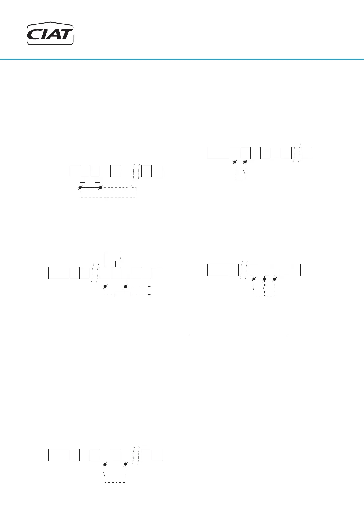
• Remote on/off
Remove the bridge from terminals 1-2 of the terminal board (located
in the electric panel) and connect a C1 contact.
* Open contact → stopped unit.
* Closed contact → unit ready to operate.
* Characteristics of the input: 24 Vdc - 15 mA.
1 2 43 6 105 11
J6 (CPU)
CA
C1
Connector
1
2
• General failure alarm
Connect the general failure indicator or alarm between terminals 7-8.
Characteristics of the output: 250 Vac - 2 A.
1 2 11 12 13 14 15 16
J3 (CPU)
230 V
Alarm
Connector
7
8
• Control of the circulation pump (LP/ILP models)
Terminals 17-18: thermal contact connection for the pump (remove
the bridge).
Characteristics of the output: 250 Vac - 2 A.
Terminal 9: connection of the pump contact.
Terminal 10: connection of the buffer tank heater contact.
• Selection of setpoint 1/setpoint 2
Connect a C2 contact between terminals 21-22.
* Open contact → COOLING mode operation.
* Closed contact → HEATING mode operation.
* Characteristics of the input: 24 Vdc - 15 mA.
1 2 43 6 105 11
J6 (CPU)
C2
Connector
22 21
Important : all contacts must be good quality and free from any polarity.
• Disconnection of power stages (2-compressor models)
Connect one contact for compressor no. 1 between terminals 40-41
and another contact for compressor no. 2 between terminals 42-41.
* Open contact → normal operation.
* Closed contact → disconnected compressor.
* Characteristics of the input: 24 Vdc - 15 mA.
1 98 107 11
J6 (CPU)
No.1 No.2
Connector
Stage
40 42 41
• Selection of cooling/heating mode (heat pump models)
Connect a C3 contact between terminals 3-4 of the ADD1 terminal
board plate.
* Open contact → COOLING mode operation.
* Closed contact → HEATING mode operation.
* Characteristics of the input: 24 Vdc - 15 mA.
1 2 43 6 95
J4 (ADD1)
C3
Connector
3 4