Installation 2-5
3902 Service Delivery Switch Hardware Installation and Start-up Manual
009-3205-001 Standard Revision D
Copyright
©
2013-2015 Ciena
®
Corporation July 2015
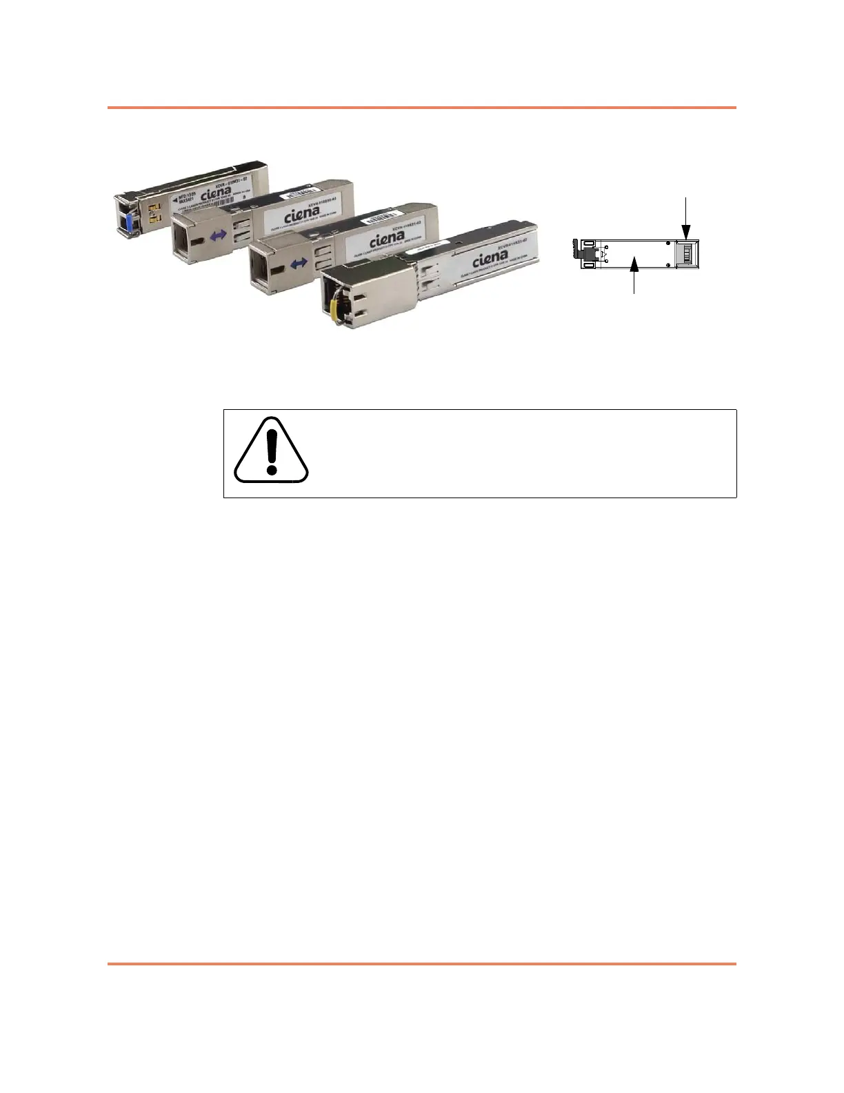
Figure 2-3
Pluggable Optic modules
For a procedure see “Installing an SFP” on page 2-9.
Installing the Interface Cabling
The 3902 uses two different types of interface cables:
• Fiber Optic Cable — used in an optical SFP on the Gigabit Ethernet port.
• Ethernet Cable — used in a copper SFP on the Gigabit Ethernet port, in
the 10/100/1000 Mbps Ethernet port and in the Console port.
Fiber Optic Cable
The 1G SFP port on the 3902 uses a pluggable optic. Using a pluggable for
this port allows you to select the port speed, wavelength, etc. to match the
device at the terminating end. See “Installing the SFP” on page 2-4 for more
information about the transceivers, and their installation.
Most SFP ports will require optical cables. You will need to know the
specification of the optic to select the appropriate cable.
Note: Do not remove the dust covers from the SFP optic and optical cable
until immediately prior to mating the connectors.
See “Gigabit Ethernet Port LED” on page 4-3 for LED information.
For a procedure see “Installing a Fiber Optic Cable” on page 2-10.
Ethernet Cable
The following ports on the 3902 have RJ-45 jacks:
• Console Port
WARNING
All electrical connections are intended for indoor use only.
20-pin connector
Bottom of module