MIG (GMAW) WELDING 5-8 Manual 0-5492
5.08 Wire Reel Brake
The wire reel hub incorporates a friction brake which is adjusted during manufacture for optimum breaking.
If it is considered necessary, adjustment can be made by turning the large nut inside the open end of the hub
clockwise to tighten the brake. Correct adjustment will result in the wire reel circumference continuing no
further than 10-20mm after release of the trigger. The wire should be slack without becoming dislodged from
wire spool.
CAUTION
Overtension of brake will cause rapid wear of mechanical WIREFEED parts, overheating of electrical componentry and
possibly an increased incidence of electrode wire Burnback into contact tip.
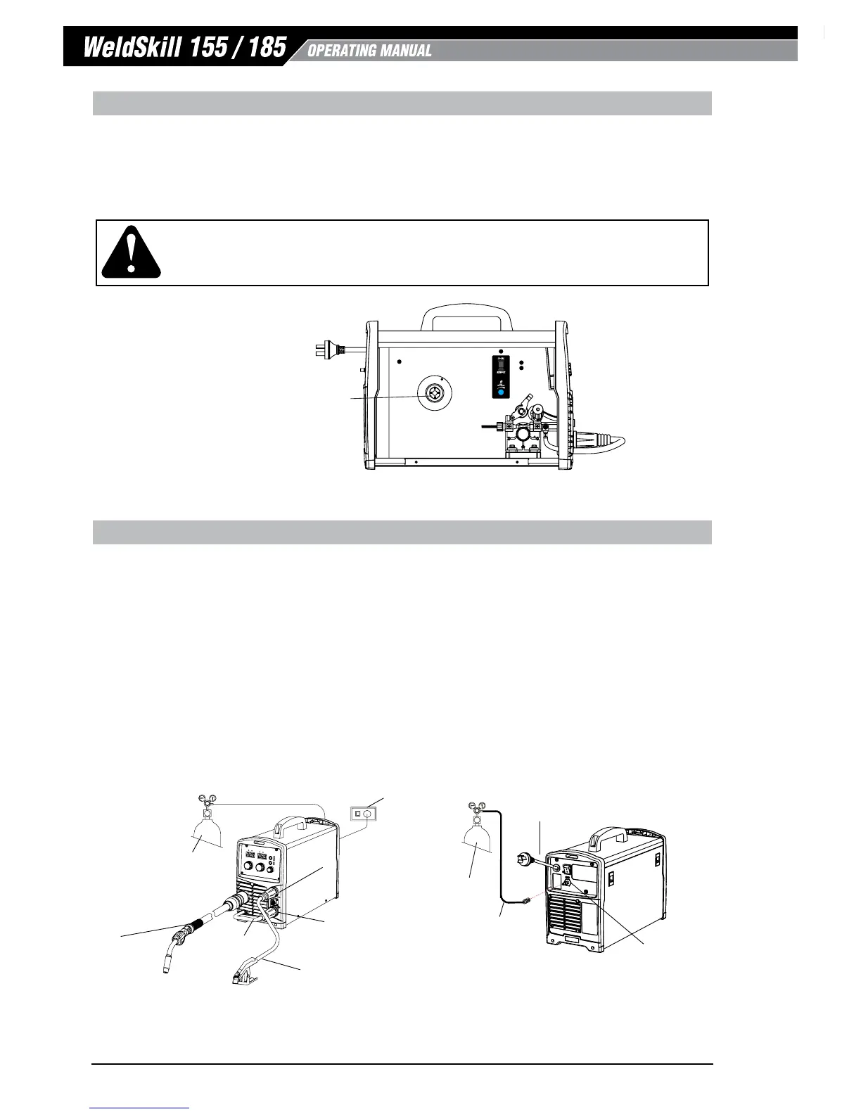
Figure 5-10: Wire Reel Brake
5.09 Setup for MIG (GMAW) Welding with Gas Shielded Mig Wire
A. Fit the MIG Torch to the Power Source. (Refer to section 5.02 Attaching the MIG Torch).
B. Connect the Mig torch polarity lead to the positive welding terminal (+). If in doubt, consult the wire
manufacturer. Welding current flows from the Power Source via Dinse terminals. It is essential, however,
that the male plug is inserted and turned securely to achieve a sound electrical connection.
C. Switch the Power Source On/Off switch located on the rear of the Power Source to the On position and
ensure the Power indicator on the Front Panel is illuminated. Set the MIG Torch trigger switch operation
either 2T or 4T mode (WeldSkill 185 only). Refer to section 4.02.2.
D. Select MIG mode with the process selection control. (refer to Section 4.02.1 for further information).
E. Fit the correct Feed Roll for the Gas Shielded MIG wire being used. Refer to section 2.11 Options and
Accessories for Feed Roll types and Part Numbers
Art # A-13448
Shielding Gas Hose
Fitted with Quick
Connect
Supply Input Lead
MIG Polarity Lead
Shielding Gas Cylinder
240VAC
10A
Mains Supply
Negative Welding Terminal
Positive Welding Terminal
Work Lead
MIG Torch
Shielding Gas Cylinder
Gas Inlet Connection
Figure 5-11: Setup for Mig Welding with Gas Shielded Mig Wire