2-12
Cisco Video Surveillance 5010/5011 Indoor Fixed HD IP Dome Camera User Guide
OL-22669-01
Chapter 2 Installation
Wiring
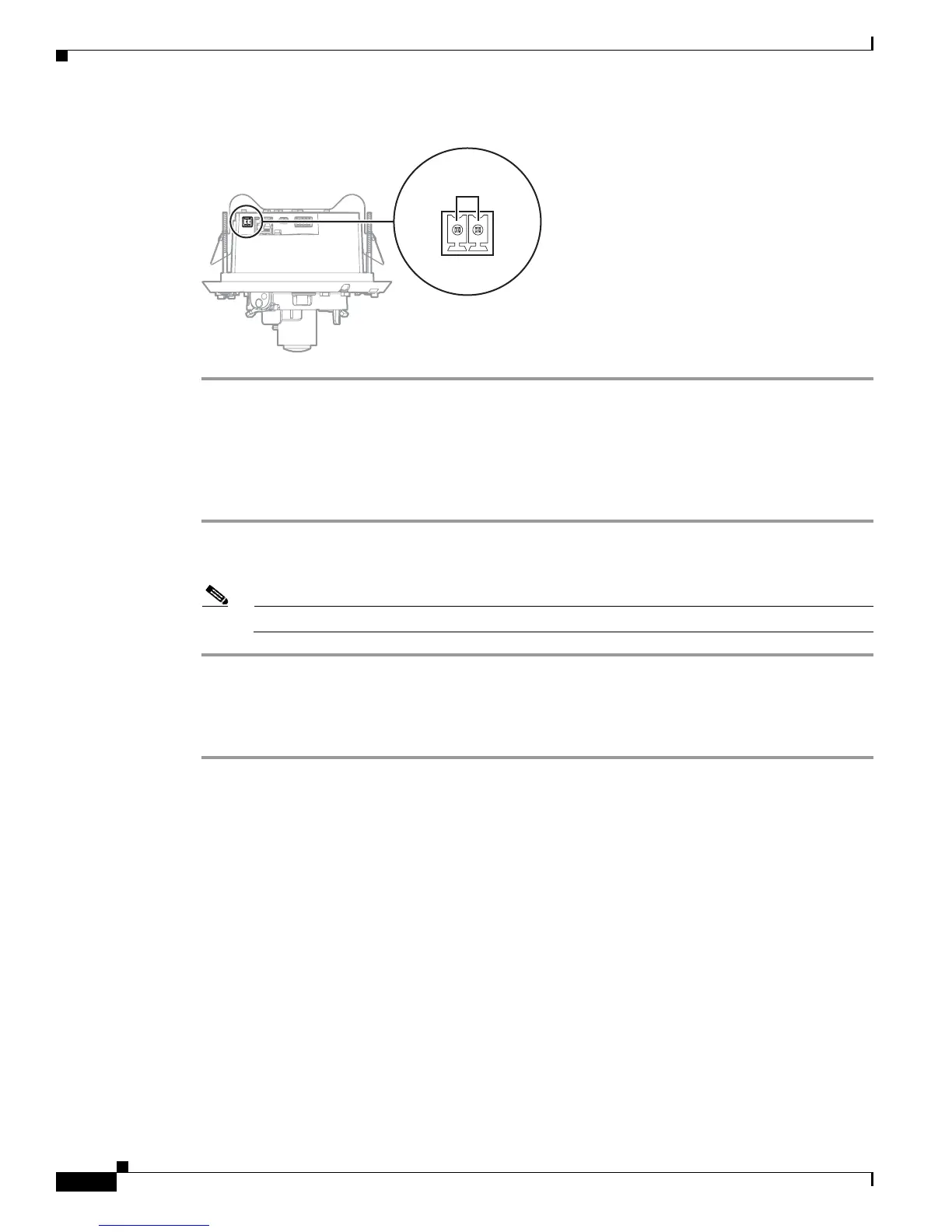
Figure 2-14 24 VAC Connector
24V~
279084
Multiple Camera Wiring
If you are operating the camera using 24 VAC and you are wiring more than one camera to the same
transformer:
Step 1 Connect one side of the transformer to pin 1 of the 2-position terminal block on all modules.
Step 2 Connect the other side of the transformer to pin 2 of the terminal block on all modules.
Note Failure to connect all modules identically might introduce video noise for some installations
Alarm and Relay Connector
Step 1 Connect the alarm and relay wires to the supplied 4-pin connector (refer to Figure 2-15).
Step 2 Attach the mating connector to the green connector on the side of the camera.