3-6
Cisco 7600 Series Router SIP, SSC, and SPA Hardware Installation Guide
OL-5052-08
Chapter 3 Overview: Cisco 7600 Series Router Shared Port Adapters
2-Port and 4-Port Clear Channel T3/E3 SPA Overview
Note The Cisco cable part numbers are 72-4124-01 ( with Male BNC end) and 72-4131-01 (with Female BNC
end).
Figure 3-1 shows the Siemax connectors on the 2-Port and 4-Port Channelized T3 SPA, and Table 3-3
provides the signal descriptions for these connectors.
2-Port and 4-Port Clear Channel T3/E3 SPA Overview
The following sections describe the 2-Port and 4-Port Clear Channel T3/E3 SPA:
• 2-Port and 4-Port Clear Channel T3/E3 SPA LEDs, page 3-6
• 2-Port and 4-Port Clear Channel T3/E3 SPA Interface Specifications, page 3-7
• 2-Port and 4-Port Clear Channel T3/E3 SPA Cables and Connectors, page 3-7
2-Port and 4-Port Clear Channel T3/E3 SPA LEDs
The 2-Port and 4-Port Clear Channel T3/E3 SPA has three types of LEDs. There are two LEDs for each
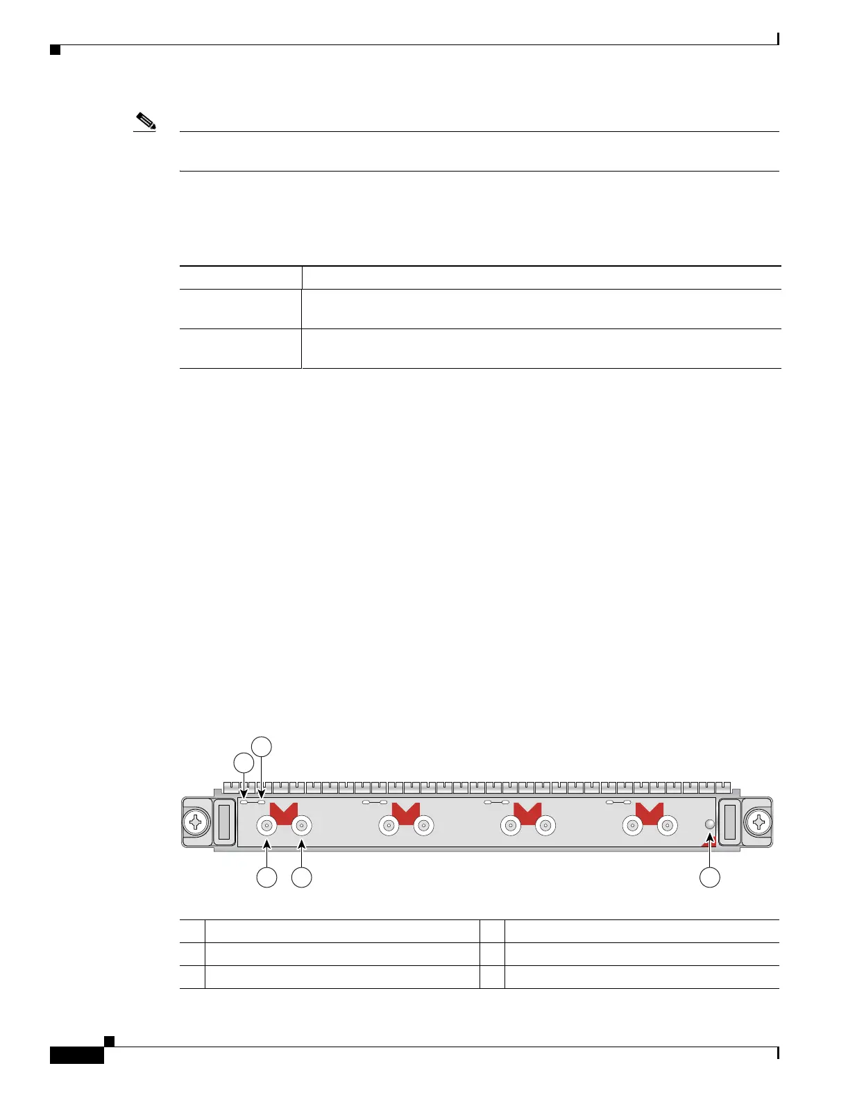
port on the SPA, and one STATUS LED. Figure 3-2 shows an example of these LEDs on a 4-Port Clear
Channel T3/E3 SPA.
Figure 3-2 4-Port Clear Channel T3/E3 SPA Faceplate
Table 3-3 2-Port and 4-Port Channelized T3 SPA Connectors
Connector Label Meaning
TX Transmitted signals appear on the center contact, and the outer shield is ground
for the 75-ohm RG-59 coaxial cable you attach to the TX Siemax connector.
RX Received signals appear on the center contact, and the outer shield is ground for
the 75-ohm RG-59 coaxial cable you attach to the RX Siemax connector.
1 C/A (Carrier/Alarm) LED 4 RX (Receive) connector
2 A/L (Active Loopback) LED 5 STATUS LED
3 TX (Transmit) connector
C/A
TX
RX
1
STATUS
SPA-4XT3/E3
0
A/L
C/A
TX
RX
A/L
C/A
TX
RX
2
A/L
C/A
TX
RX
3
A/L
1
2
3 4 5
116851

 Loading...


