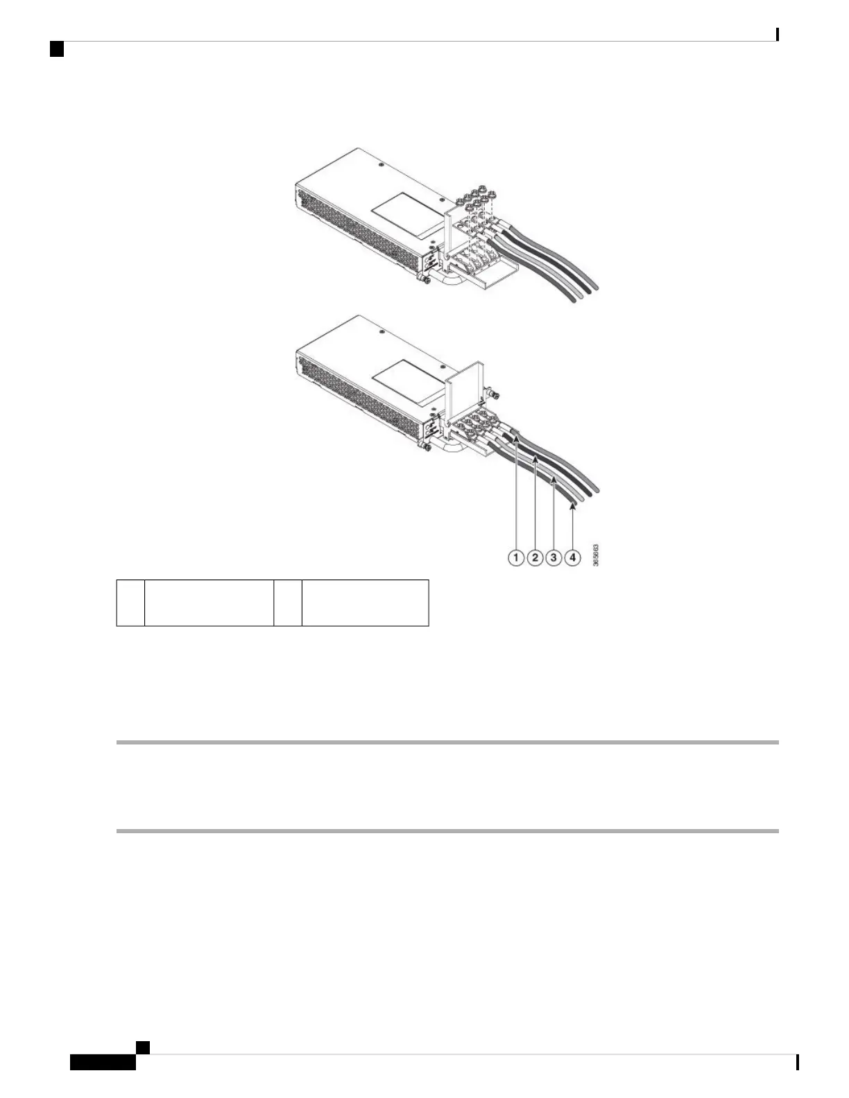
Figure 75: Power Supply with Lead Wires
Positive (+) lead wire2,
4
Negative (-) lead wire1,
3
Do not overtorque the fasteners of the terminal block. The recommended maximum torque is from 25 in.-lb
(2.82 N-m).
Caution
Step 6 Use a tie wrap to secure the wires to the rack, so that the wires are not pulled from the terminal block by casual contact.
Make sure the tie wrap allows for some slack in the wire.
Activating the DC Power Supply
Perform the following procedure to activate the DC power supply:
Step 1 Remove the tape from the circuit-breaker switch handle, and restore power by moving the circuit-breaker switch handle
to the On (|) position.
Step 2 Verify power supply operation by checking if the power supply front panel LEDs are in the following states:
• INPUT OK LED is green
• OUTPUT FAIL LED is red
Cisco ASR 903 and ASR 903U Aggregation Services Router Hardware Installation Guide
100
Installing the Cisco ASR 903 Router
Activating the DC Power Supply

 Loading...


