T1/E1 Port Pinout
RJ48 T1/E1 Port Pinouts
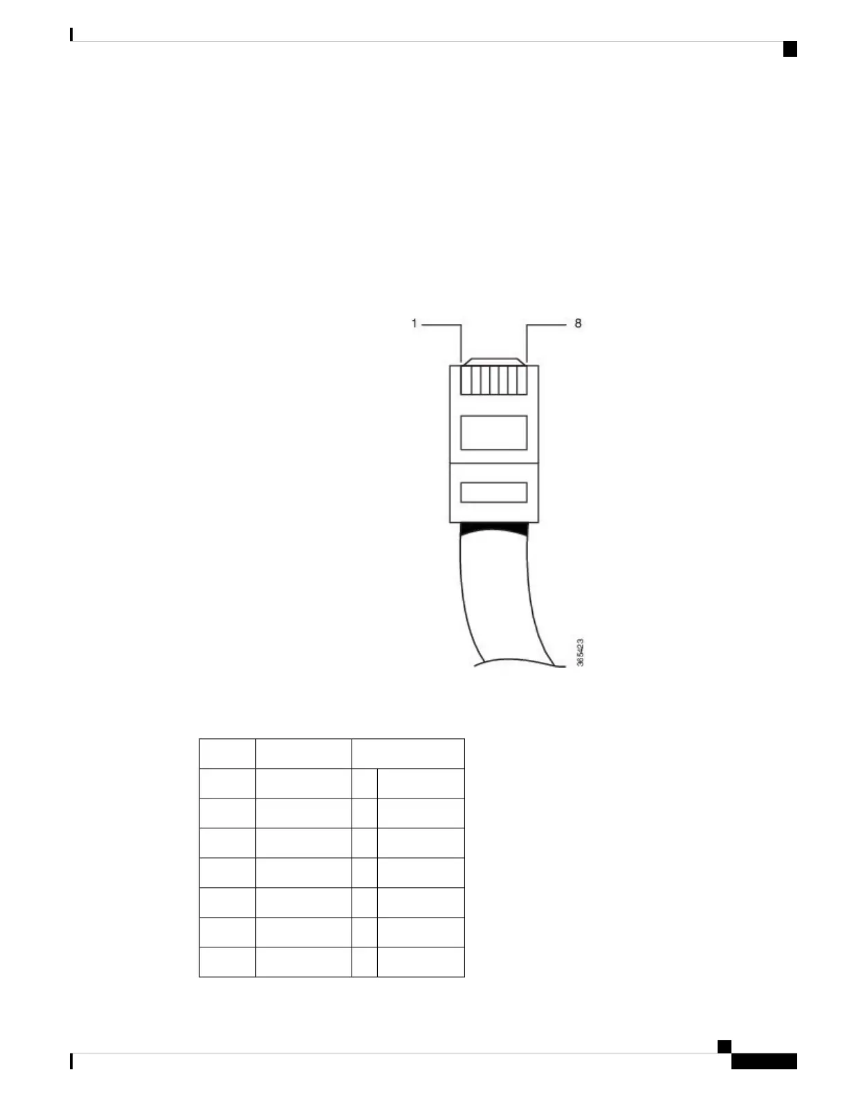
The figure below shows the RJ48 connector wiring for the T1/E1 cable for the interface module. The table
shows the pinout configuration for the RJ4C connectors for both the shielded and unshielded cables for either
T1 or E1.
Figure 120: RJ48 Connector Wiring
The table below summarizes the RJ48 port pinout.
Table 35: RJ48 Port Pinouts
UnshieldedShielded
DescriptionPinDescriptionPin
Receive Ring1Receive Ring1
Receive Tip2Receive Tip2
3Receive Shield3
Transmit Ring4Transmit Ring4
Transmit Tip5Transmit Tip5
6Transmit Shield6
Cisco ASR 903 and ASR 903U Aggregation Services Router Hardware Installation Guide
171
Troubleshooting
T1/E1 Port Pinout

 Loading...


