• Front panel access to power supplies, fan tray, RSPs, and interface modules
• Online insertion and removal (OIR) of RSP, interface modules, power supplies, and fan tray
• Discrete status LEDs on power supply, interface module, RSP, and fan tray units
• Four alarm dry contact inputs (either normally open or normally closed)
• Environmental monitoring and reporting functions
• LED indicators for critical, major, and minor alarms
• Side-to-side forced air cooling
• Temperature range, see Cisco ASR 900 Series Aggregation Services Routers Data Sheet.
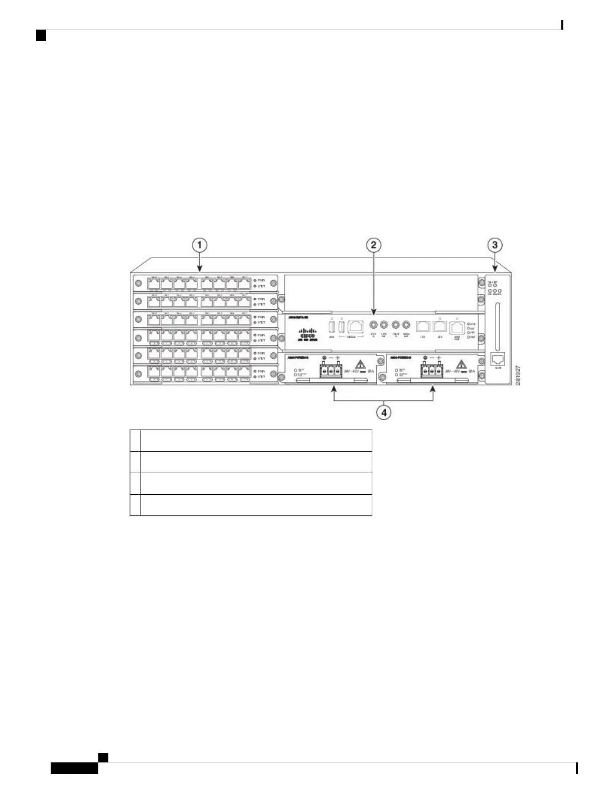
The figure below illustrates the Cisco ASR 903 Router chassis design.
Figure 1: Cisco ASR 903 Router Chassis Design
Interface modules1
RSP unit (with active and standby RSP slots)2
Fan tray3
Redundant power units (two DC power units are shown)4
Power Supply Features
The Cisco ASR 903 Router support AC and DC power supplies. For more information about installing the
Cisco ASR 903 Router power supplies, see the Installing the Power Supply.
To estimate the required power supply, use the Cisco Power Calculator.
The power sections provide more information about the power supply:
Redundancy
The Cisco ASR 903 Router chassis includes a slot for an optional redundant power supply. The redundant
power supply option provides a second power supply to ensure that power to the chassis continues uninterrupted
if one power supply fails or input power on one line fails. Redundancy is supported either with identical power
Cisco ASR 903 and ASR 903U Aggregation Services Router Hardware Installation Guide
2
Overview
Power Supply Features

 Loading...


