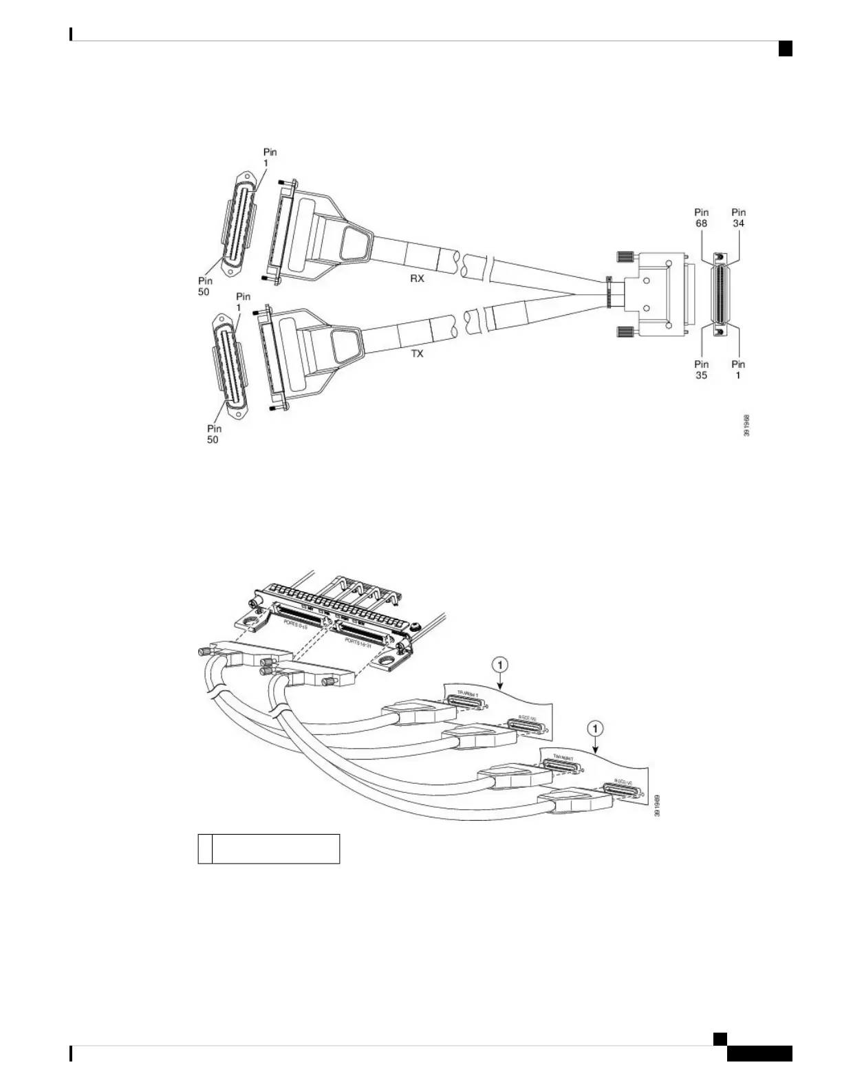
Figure 85: 32 x T1/E1 Cable Connector
The other end of the cable has two 50-pin Telco connectors that attach to the rear of a 24-port RJ45 patch
panel. Both connectors are identical: one is for Transmit (TX) and the other is for Receive (RX).
The figure below shows how the cable is connected between the 32 x T1/E1 interface module and the patch
panel.
Figure 86: Cable Installation between 32 x T1/E1 Interface and Patch Panel
Patch panel interfaces1
Cisco ASR 903 and ASR 903U Aggregation Services Router Hardware Installation Guide
121
Installing the Cisco ASR 903 Router
32 x T1/E1 Cable Connector

 Loading...


