1-3
Catalyst 3550 Multilayer Switch Hardware Installation Guide
78-11358-01
Chapter 1 Product Overview
Front-Panel Description
Front-Panel Description
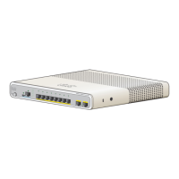
The front panel of the Catalyst 3550 switch has ten 10/100/1000 RJ-45 ports, two
GBIC module slots, a set of LEDs, and a Mode button. (See Figure 1-2 and
Figure 1-3). The 10/100/1000 ports are numbered 1 through 10 (port 1 is on the
far left), and the GBIC slot numbers are 11 (top) and 12 (bottom).
Figure 1-2 Catalyst 3550 Front Panel
10/100/1000 Ports
The 10/100/1000 switch ports on the Catalyst 3550 can be explicitly set to operate
in any combination of half duplex, full duplex, 10 Mbps, 100 Mbps, or
1000 Mbps. These ports also can be set for speed and duplex autonegotiation,
compliant with IEEE 802.3ab. (The default setting is autonegotiate.) When set for
autonegotiation, the port senses the speed and duplex settings of the attached
device and advertises its own capabilities. If the connected device also supports
autonegotiation, the switch port negotiates the best connection (that is, the fastest
line speed that both devices support and full-duplex transmission if the attached
device supports it) and configures itself accordingly. In all cases, the attached
device must be within 100 meters.
M
O
D
E
S
Y
S
T
E
M
R
P
S
S
T
A
T
U
S
U
T
I
L
D
U
P
L
X
S
P
E
E
D
1
2
1
1
1
Catalyst 3550
2
3
4
5
6
7
8
9
1
0
10/100/1000
ports
GBIC
module slots
50373

 Loading...


