Chapter 2 Installing and Starting the Switch
Installing the Switch
2-14
Catalyst 3550 Multilayer Switch Hardware Installation Guide
78-11358-01
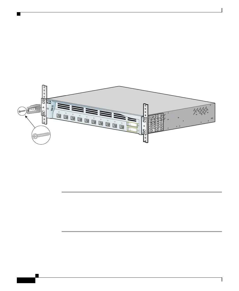
Attaching the Optional Cable Guide
We recommend attaching the cable guide to prevent the cables from obscuring the
front panel of the switch and the other devices installed in the rack. If the switch
is in a 19-inch or 24-inch rack, use the supplied black screw, as shown in
Figure 2-6, to attach the cable guide to the left or right bracket.
Figure 2-6 Attaching the Cable Guide
Table or Shelf Mounting
Follow these steps to install the switch on a table or shelf:
Step 1 Locate the adhesive strip with the rubber feet in the mounting-kit envelope.
Attach the four rubber feet to the recessed areas on the bottom of the unit.
Step 2 Place the switch on the table or shelf near an AC power source.
After the switch is mounted on the table or shelf, see “Powering On the Switch
and Running POST” section on page 2-17 to complete the installation.
M
O
D
E
S
Y
S
T
E
M
R
P
S
S
T
A
T
U
S
U
T
IL
D
U
P
L
X
S
P
E
E
D
2
1
1
C
atalyst 3
550
2
3
4
5
6
7
8
9
1
0
51367
Cable guide screw