• Stratum 3E network clocking per GR-1244-CORE, using 1 GE, 10 GE, or EPA interfaces as timing
sources.
• LED indicators for Ethernet and console status, as well as visual system state indications.
• Command-line interface (CLI), alarm, network management, logging, statistics aggregation, and on-board
failure logging (OBFL).
• Environmental chassis management.
• 80 Mb ternary content-addressable memory (TCAM).
• Field-replaceable units (FRU).
See Chapter 2, Supported Hardware Components for information on supported FRUs.
Front View
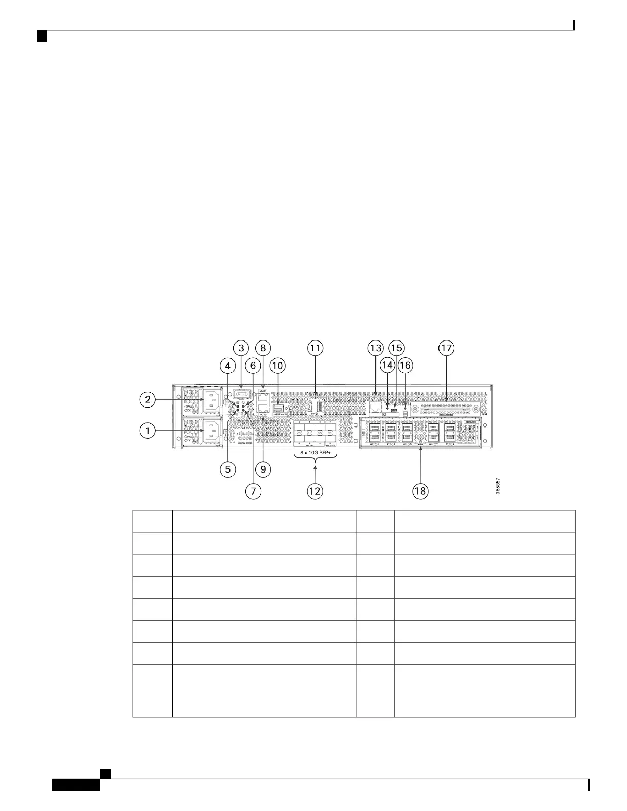
The following figure shows the front of the Cisco Catalyst 9800-80 Wireless Controller.
Figure 1: Cisco Catalyst 9800-80 Wireless Controller Front View
RP— 1-GE SFP port10Power supply (PEM 0)1
USB ports 0 and 111Power supply (PEM 1)2
Bay 0—8 X 10GE SFP+ ports (Fixed EPA)12Power (PWR) switch3
CON— RJ-45 compatible console port13PWR— Power LED4
LINK— RJ-45 connector LED14SYS— System LED5
CON— Mini USB console port15ALM— Alarm LED6
SSD— SSD activity LED16HA— High-Availability LED7
SSD Access17SP— RJ-45 10/100/1000 management
Ethernet
port
8
Cisco Catalyst 9800-80 Wireless Controller Hardware Installation Guide
2
Overview
Front View