You can later configure the device manager management access from other interfaces; see the FDM
configuration guide.
Step 3 Connect the outside network to the Ethernet1/1 interface (labeled WAN).
By default, the IP address is obtained using IPv4 DHCP and IPv6 autoconfiguration, but you can set a static
address during initial configuration.
Step 4 Connect other networks to the remaining interfaces.
Power on the Device
The power switch is located to the left of power supply module 1 on the rear of the chassis. It is a toggle
switch that controls power to the system. If the power switch is in standby position, only the 3.3-V standby
power is enabled from the power supply module and the 12-V main power is OFF. When the switch is in the
ON position, the 12-V main power is turned on and the system boots.
The first time you boot up the threat defense, initialization can take approximately 15 to 30 minutes.
Note
Before you begin
It's important that you provide reliable power for your device (for example, using an uninterruptable power
supply (UPS)). Loss of power without first shutting down can cause serious file system damage. There are
many processes running in the background all the time, and losing power does not allow the graceful shutdown
of your system.
Procedure
Step 1 Attach the power cord to the device and connect it to an electrical outlet.
Step 2 Press the power switch on the back of the device.
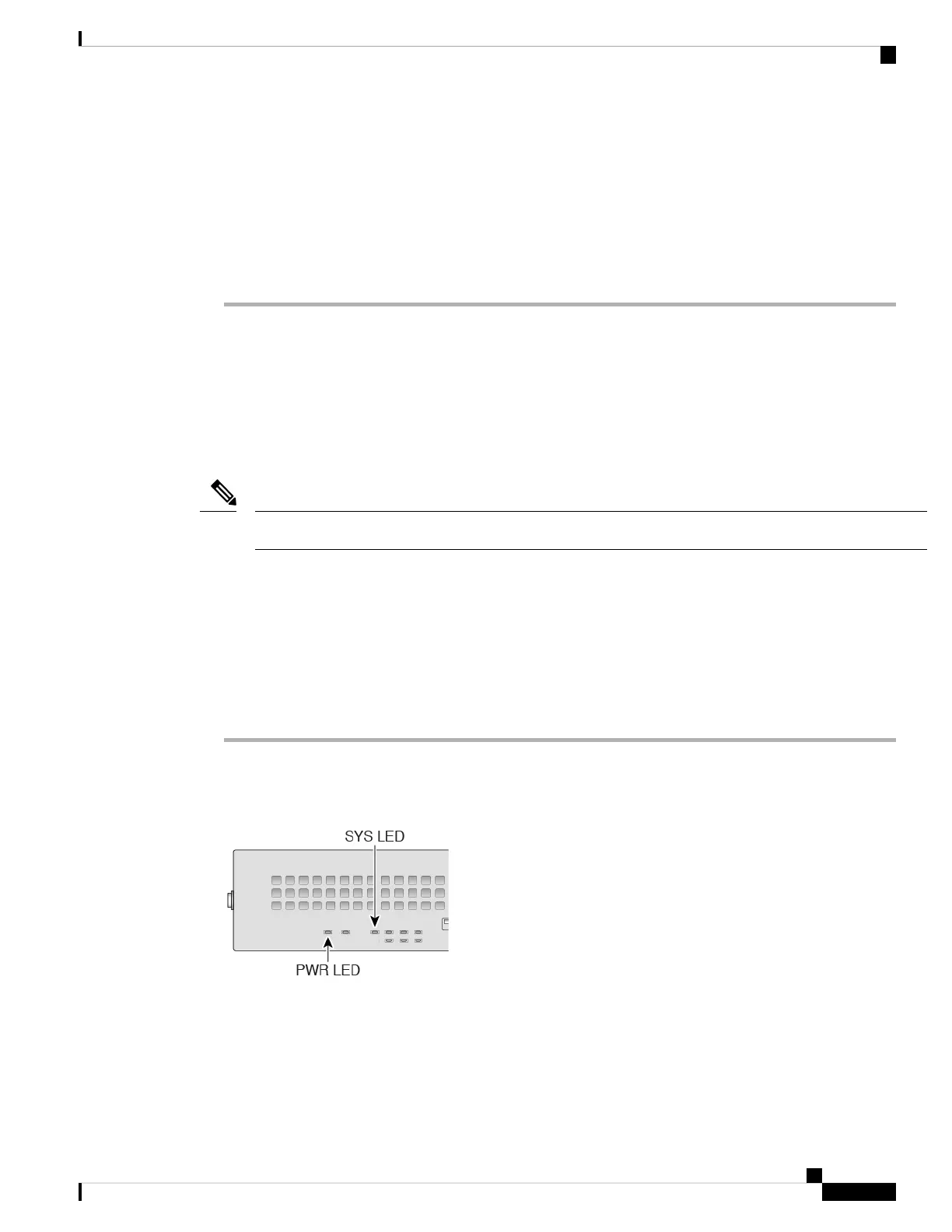
Step 3 Check the PWR LED on the front of the device; if it is solid green, the device is powered on.
Step 4 Check the SYS LED on the front of the device; after it is solid green, the system has passed power-on
diagnostics.
Cisco Firepower 2100 Getting Started Guide
105
Threat Defense Deployment with the Device Manager
Power on the Device
 Loading...