Step 5
To prevent any contact with metal lead on the ground wire and the plastic cover, you must wrap the positive and negative
lead cables with sleeving. Insulate the lug with shrink sleeving for each lead wire if using noninsulated crimp terminals.
Sleeving is not required for insulated terminals.
Step 6
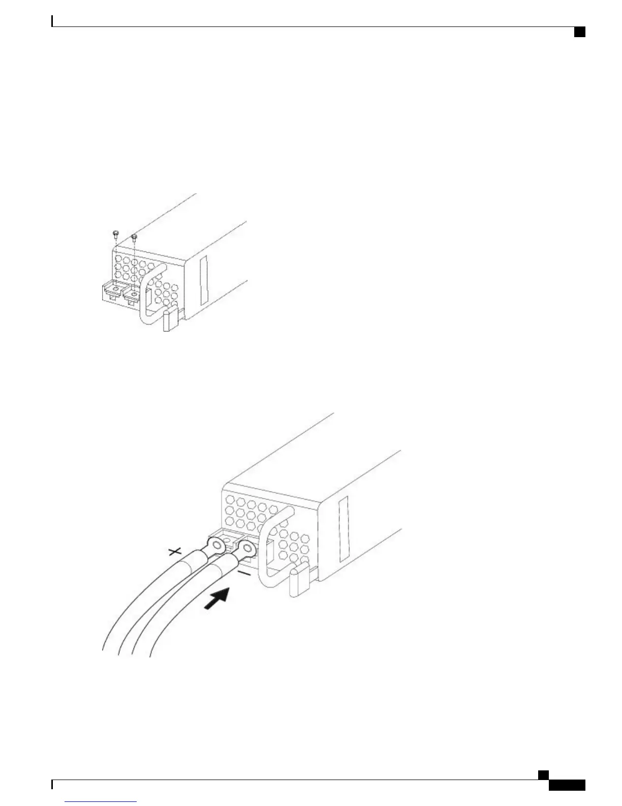
Remove the two M5 screws.
Figure 47: Remove the M5 Screws
Step 7
For easier cable management, insert the negative lead cable first. Replace the grounding lug with the cable in the following
order—wire terminal, then the screw with the captive washer.
Figure 48: Insert the Cables
Cisco Firepower 4100 Series Hardware Installation Guide
73
Maintenance and Upgrades
Connect the DC Power Supply Module
 Loading...


