17-10
Cisco Security Appliance Command Line Configuration Guide
OL-10088-01
Chapter 17 Applying NAT
NAT Overview
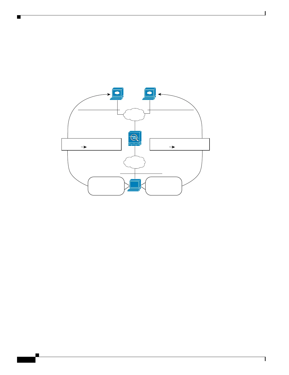
Figure 17-8 shows a host on the 10.1.2.0/24 network accessing two different servers. When the host
accesses the server at 209.165.201.11, the real address is translated to 209.165.202.129. When the host
accesses the server at 209.165.200.225, the real address is translated to 209.165.202.130 so that the host
appears to be on the same network as the servers, which can help with routing.
Figure 17-8 Policy NAT with Different Destination Addresses
See the following commands for this example:
hostname(config)# access-list NET1 permit ip 10.1.2.0 255.255.255.0 209.165.201.0
255.255.255.224
hostname(config)# access-list NET2 permit ip 10.1.2.0 255.255.255.0 209.165.200.224
255.255.255.224
hostname(config)# nat (inside) 1 access-list NET1
hostname(config)# global (outside) 1 209.165.202.129
hostname(config)# nat (inside) 2 access-list NET2
hostname(config)# global (outside) 2 209.165.202.130
Server 1
209.165.201.11
Server 2
209.165.200.225
DMZ
Inside
10.1.2.27
10.1.2.0/24
130039
209.165.201.0/27 209.165.200.224/27
Translation
209.165.202.12910.1.2.27
Translation
209.165.202.13010.1.2.27
Packet
Dest. Address:
209.165.201.11
Packet
Dest. Address:
209.165.200.225

 Loading...


