B-30
Cisco Security Appliance Command Line Configuration Guide
OL-10088-01
Appendix B Sample Configurations
Example 12: LAN-Based Active/Active Failover (Transparent Mode)
Example 12: LAN-Based Active/Active Failover (Transparent
Mode)
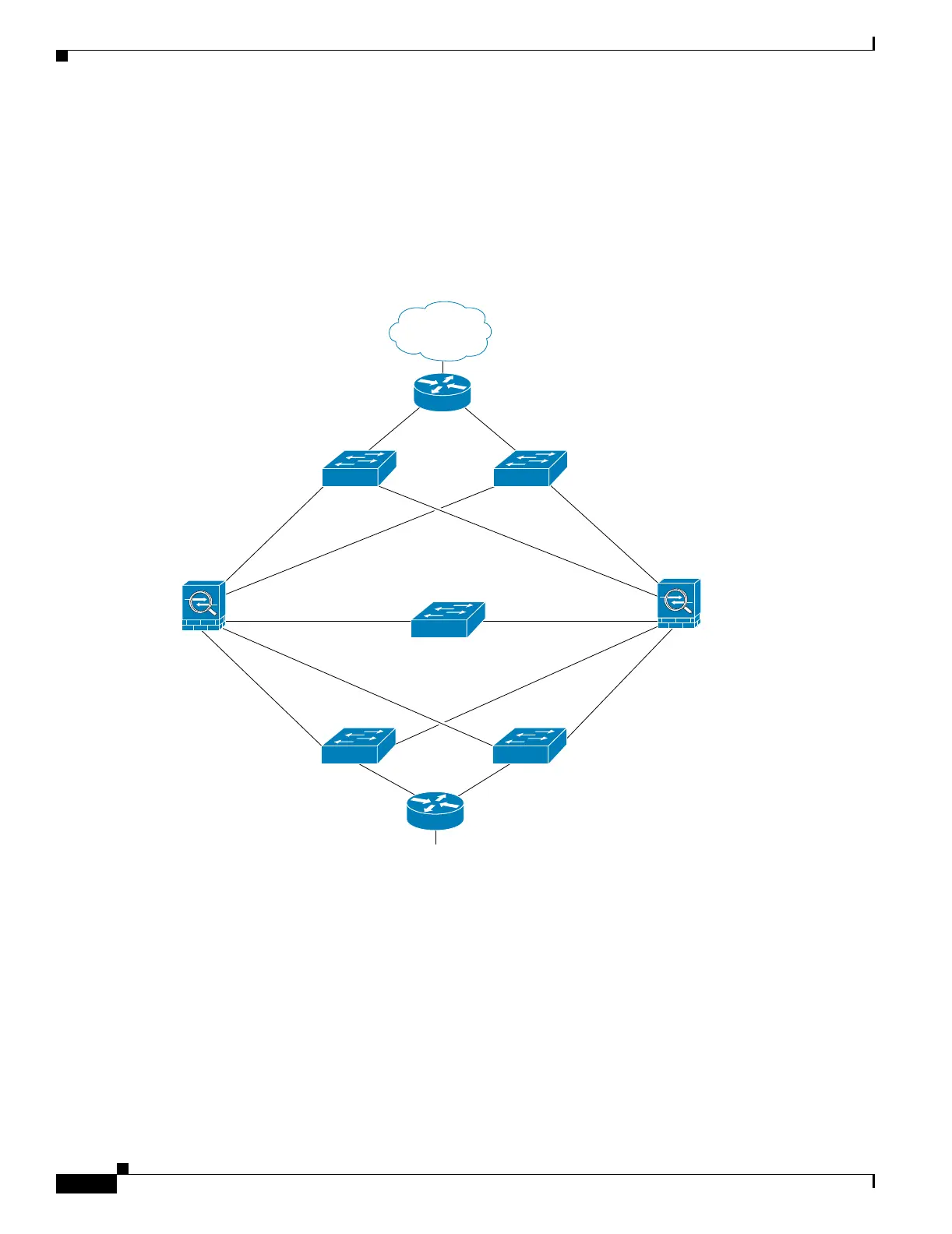
The following example shows how to configure transparent mode Active/Active failover. In this example
there are 2 user contexts, named admin and ctx1. Figure B-8 shows the network diagram for the example.
Figure B-11 Transparent Mode Active/Active Failover Configuration
See the following sections for the configurations for this scenario:
• Example 9: Primary Unit Configuration
• Example 9: Secondary Unit Configuration
Example 12: Primary Unit Configuration
See the following sections for the primary unit configuration:
• Example 9: Primary System Configuration, page B-23
• Example 9: Primary admin Context Configuration, page B-24
• Example 9: Primary ctx1 Context Configuration, page B-25
153890
Internet
Switch
Switch
Outside
192.168.10.1
192.168.5.1
Switch
Switch Switch
Inside
admin ctx1
10.0.4.1
10.0.4.11
Failover
State
192.168.5.81 192.168.10.81
Primary
Secondary
adminctx1
adminctx1
Failover Group 1
Active
Active Contexts:
-admin (192.168.5.31)
Standby Contexts:
-ctx1 (192.168.1.32)
Failover Group 2
Active
Active Contexts:
-ctx1 (192.168.10.31)
Standby Contexts:
-admin (102.168.5.32)
admin ctx1

 Loading...


