B-21
Cisco Security Appliance Command Line Configuration Guide
OL-10088-01
Appendix B Sample Configurations
Example 8: LAN-Based Active/Standby Failover (Routed Mode)
interface Ethernet3
description STATE Failover Interface
telnet 192.168.2.45 255.255.255.255 inside
access-list acl_in permit tcp any host 209.165.201.5 eq 80
access-group acl_in in interface outside
failover
failover link state Ethernet3
failover interface ip state 192.168.253.1 255.255.255.252 standby 192.168.253.2
global (outside) 1 209.165.201.3 netmask 255.255.255.224
nat (inside) 1 0.0.0.0 0.0.0.0
static (inside,outside) 209.165.201.5 192.168.2.5 netmask 255.255.255.255 0 0
route outside 0.0.0.0 0.0.0.0 209.165.201.4 1
Example 8: LAN-Based Active/Standby Failover (Routed Mode)
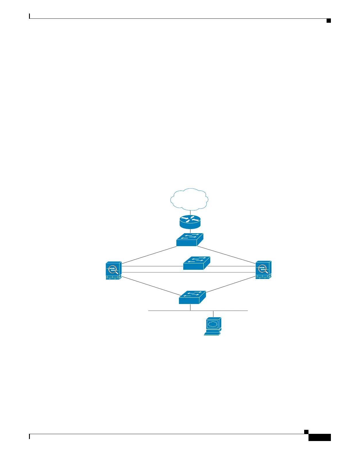
Figure B-7 shows the network diagram for a failover configuration using an Ethernet failover link. The
units are configured to detect unit failures and to fail over in under a second (see the failover polltime
unit command in the primary unit configuration).
Figure B-7 LAN-Based Failover Configuration
See the following sections for the configurations for this scenario:
• Example 8: Primary Unit Configuration, page B-21
• Example 8: Secondary Unit Configuration, page B-22
Example 8: Primary Unit Configuration
hostname pixfirewall
enable password myenablepassword
Internet
209.165.201.4
192.168.254.1
192.168.253.1
192.168.254.2
192.168.253.2
192.168.2.5
192.168.2.1
209.165.201.1
209.165.201.2
192.168.2.2
Switch
Switch
Switch
failover
state
outside
inside
PAT: 209.165.201.3
Primary Unit
Secondary Unit
Static: 209.165.201.5
Web Server
126667

 Loading...


