45
Warning: Only trained and qualified personnel should be allowed to install, replace, or service this equipment.
Statement 1030
Caution: For wire connections to the power and alarm connectors, you must use UL- and CSA-rated, style 1007 or 1569
twisted-pair copper appliance wiring material (AWM) wire (such as Belden part number 9318).
To wire the switch to a DC power source, follow these steps:
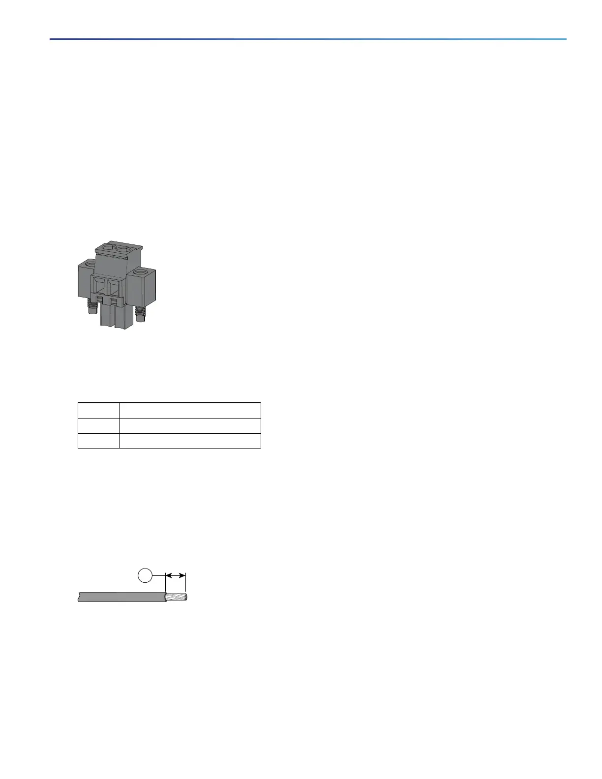
1. Locate the two power connectors on the switch front panel labeled DC-A and DC-B (see Figure 22 on page 45)
note: On the PoE-capable models of the switch, there is a third DC-input power connector on the switch front panel
labeled PoE. See Connecting Power to the Switch PoE DC-Input (Optional), page 51.
Figure 22 Power Connector
2. Identify the connector positive and return DC power connections.
The labels for power connectors DC-A and DC-B are on the switch panel as displayed in Table 12 on page 45.
3. Measure two strands of twisted-pair copper wire (18-to-20 AWG) long enough to connect to the DC power source.
4. Using an 18-gauge wire-stripping tool, strip each of the two twisted pair wires coming from each DC-input power
source to 0.25 inch (6.3 mm) ± 0.02 inch (0.5 mm).
Note: Do not strip more than 0.27 inch (6.8 mm) of insulation from the wire. Stripping more than the recommended
amount of wire can leave exposed wire from the power connector after installation.
Figure 23 Stripping the Power Connection Wire
5. Remove the two captive screws that attach the power connector to the switch, and remove the power connector.
Remove both connectors if you are connecting to two power sources. See Figure 24 on page 46.
Table 12 DC-A and DC-B Power Connector Labels
Label Connection
+ Positive DC power connection
– Return DC power connection
1 0.25 in. (6.3 mm) ± 0.02 in. (0.5 mm)