60
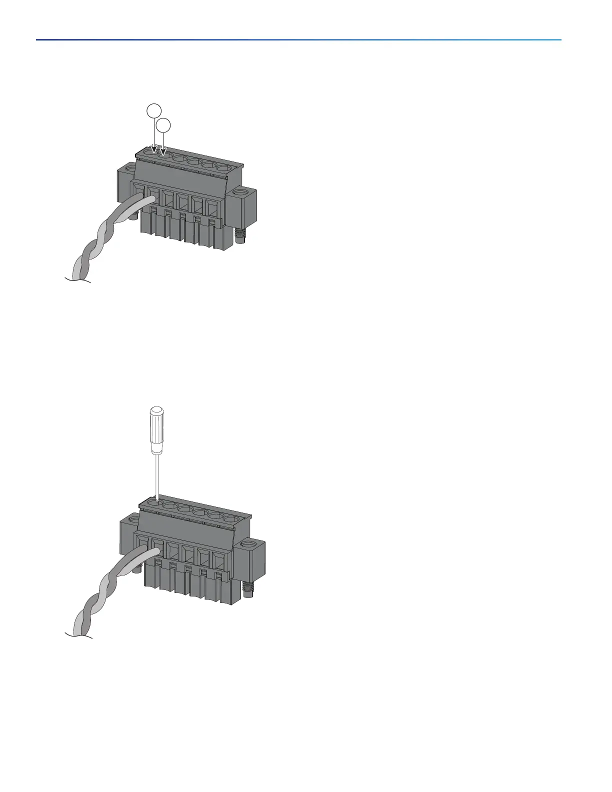
Figure 34 Inserting Wires into the Alarm Connector (Alarm Input Circuit)
5. Use a ratcheting torque flathead screwdriver to tighten the alarm connector captive screw (above the installed wire
leads) to 2 in-lb (0.23 N-m). (See Figure 35 on page 60.)
Note: Do not over-torque the power and alarm connectors’ captive screws. Do not exceed 2 inch-lbs (0.23 N-m) torque.
Figure 35 Securing the Alarm Connector Captive Screws
6. Repeat the above steps to insert the input and output wires of one additional external alarm device into the alarm
connector.
Figure 36 on page 61 shows the completed wiring for two external alarm devices. The first alarm device circuit is wired
as an alarm input circuit; the IN1 and REF connections complete the circuit. The second alarm device circuit is wired as
an alarm output circuit that works on a normally open contact basis; the NO and COM connections complete the circuit.
1 IN1 - External device connection 1 2 REF - External device connection 2