38-2
Cisco IE 3000 Switch Software Configuration Guide
OL-13018-03
Chapter 38 Configuring EtherChannels and Link-State Tracking
Understanding EtherChannels
EtherChannel Overview
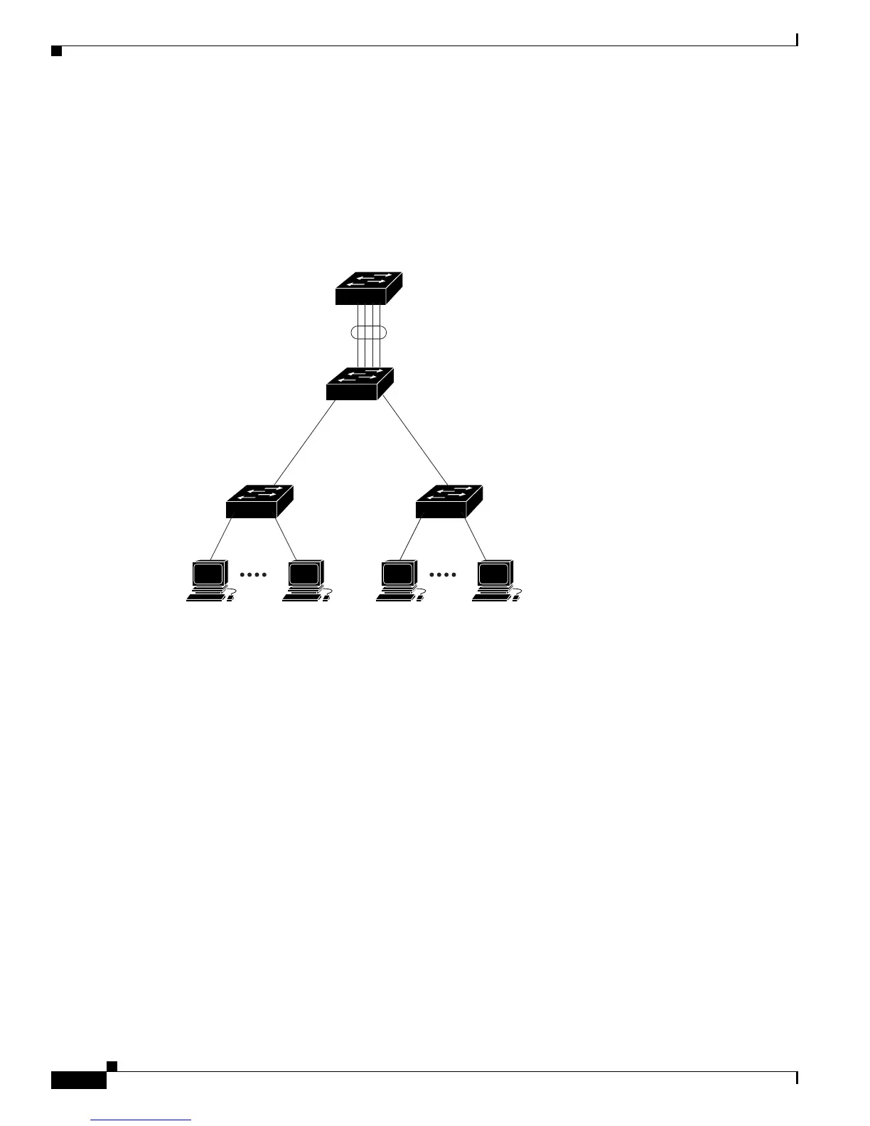
An EtherChannel consists of individual Fast Ethernet or Gigabit Ethernet links bundled into a single
logical link as shown in
Figure 38-1.
Figure 38-1 Typical EtherChannel Configuration
The EtherChannel provides full-duplex bandwidth up to 800 Mb/s (Fast EtherChannel) or 8 Gb/s
(Gigabit EtherChannel) between your switch and another switch or host.
Each EtherChannel can consist of up to eight compatibly configured Ethernet ports. All ports in each
EtherChannel must be configured as Layer
2 ports. The number of EtherChannels is limited to six. For
more information, see the
“EtherChannel Configuration Guidelines” section on page 38-9.
You can configure an EtherChannel in one of these modes: Port Aggregation Protocol (PAgP), Link
Aggregation Control Protocol (LACP), or On. Configure both ends of the EtherChannel in the same
mode:
• When you configure one end of an EtherChannel in either PAgP or LACP mode, the system
negotiates with the other end of the channel to determine which ports should become active.
Incompatible ports are put into an independent state and continue to carry data traffic as would any
other single link. The port configuration does not change, but the port does not participate in the
EtherChannel.
• When you configure an EtherChannel in the on mode, no negotiations take place. The switch forces
all compatible ports to become active in the EtherChannel. The other end of the channel (on the other
switch) must also be configured in the on mode; otherwise, packet loss can occur.
If a link within an EtherChannel fails, traffic previously carried over that failed link moves to the
remaining links within the EtherChannel. If traps are enabled on the switch, a trap is sent for a failure
that identifies the switch, the EtherChannel, and the failed link. Inbound broadcast and multicast packets
on one link in an EtherChannel are blocked from returning on any other link of the EtherChannel.
101237
Catalyst 8500
series switch
Gigabit EtherChannel
Workstations
10/100
Switched
links
Workstations
10/100
Switched
links
1000BASE-X 1000BASE-X
 Loading...


