B-20
Cisco IE 3000 Switch Hardware Installation Guide
OL-13017-01
Appendix B Installation In a Hazardous Environment
Verifying Switch Operation
Warning
Before performing any of the following procedures, ensure that power is removed from the DC circuit.
Statement 1003
Warning
Only trained and qualified personnel should be allowed to install, replace, or service this equipment.
Statement 1030
Caution You must connect the switch only to a DC-input power source that has an input supply voltage from
18 to 60 VDC. If the supply voltage is not in this range, the switch might not operate properly or might
be damaged.
Caution For wire connections to the power and relay connector, you must use UL- and CSA-rated, style 1007 or
1569 twisted-pair copper appliance wiring material (AWM) wire (such as Belden part number 9318).
To wire the switch to the optional AC/DC converter, go to the “Connecting the Switch to the Power
Converter” section on page B-49.
To wire the switch to a DC-input power source, follow these steps:
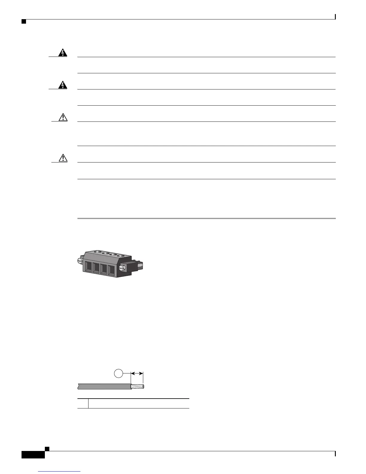
Step 1 Locate the power and relay connector (see Figure B-12).
Figure B-12 Power and Relay Connector
Step 2 Identify the positive and return DC power connections on the connector. The positive DC power
connection is labeled V, and the return is the adjacent connection labeled RT. See
Figure B-12.
Step 3 Measure two strands of twisted-pair copper wire (18-to-20 AWG) long enough to connect to the DC
power source.
Step 4 Using an 18-gauge wire-stripping tool, strip each of the two twisted pair wires coming from each
DC-input power source to 0.25 inch (6.3 mm) ± 0.02 inch (0.5 mm). Do not strip more than 0.27 inch
(6.8 mm) of insulation from the wire. Stripping more than the recommended amount of wire can leave
exposed wire from the power and relay connector after installation.
Figure B-13 Stripping the Power Connection Wire
201815
RT
A
V
A
1 0.25 in. (6.3 mm) ± 0.02 in. (0.5 mm)
97489
1

 Loading...


