B-58
Cisco IE 3000 Switch Hardware Installation Guide
OL-13017-01
Appendix B Installation In a Hazardous Environment
Connecting the Switch to the Power Converter
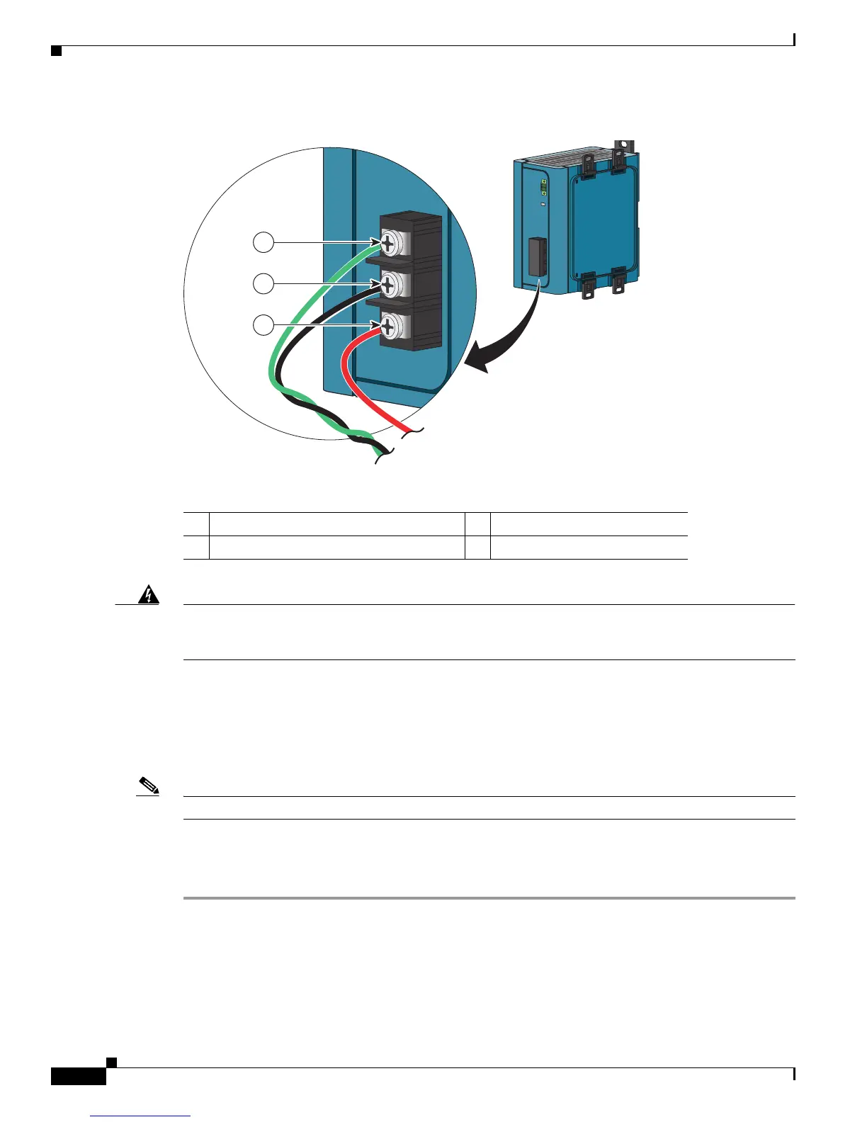
Figure B-45 AC/DC Power Input Terminal Block Wire Connections to a DC Source
Warning
An exposed wire lead from a DC-input power source can conduct harmful levels of electricity. Be sure
that no exposed portion of the DC-input power source wire extends from the power and relay
connector.
Statement 122
Step 7 Insert the twisted-pair wire leads into the terminal block line and neutral connections. Insert the wire
(labeled number 1 in Figure B-45) lead into the neutral wire connection and the wire (labeled
number 2 in Figure B-45) lead into the line wire connection. Ensure that only wire with insulation
extends from the connectors. See Figure B-45.
Step 8 Tighten the line and neutral terminal block screws.
Note The torque should not exceed 10 in-lb.
Step 9 Connect the red wire to the positive pole of the DC power source, and connect the black wire to the return
pole. Ensure that each pole has a current-limiting-type fuse rated to at least 600 VAC/DC (such as the
KLKD Midget fuse).
1 Earth ground wire connection 3 Positive DC connection
2 Return wire connection (to DC return)
202301
3
2
1

 Loading...


