B-54
Cisco IE 3000 Switch Hardware Installation Guide
Appendix B Installation In a Hazardous Environment
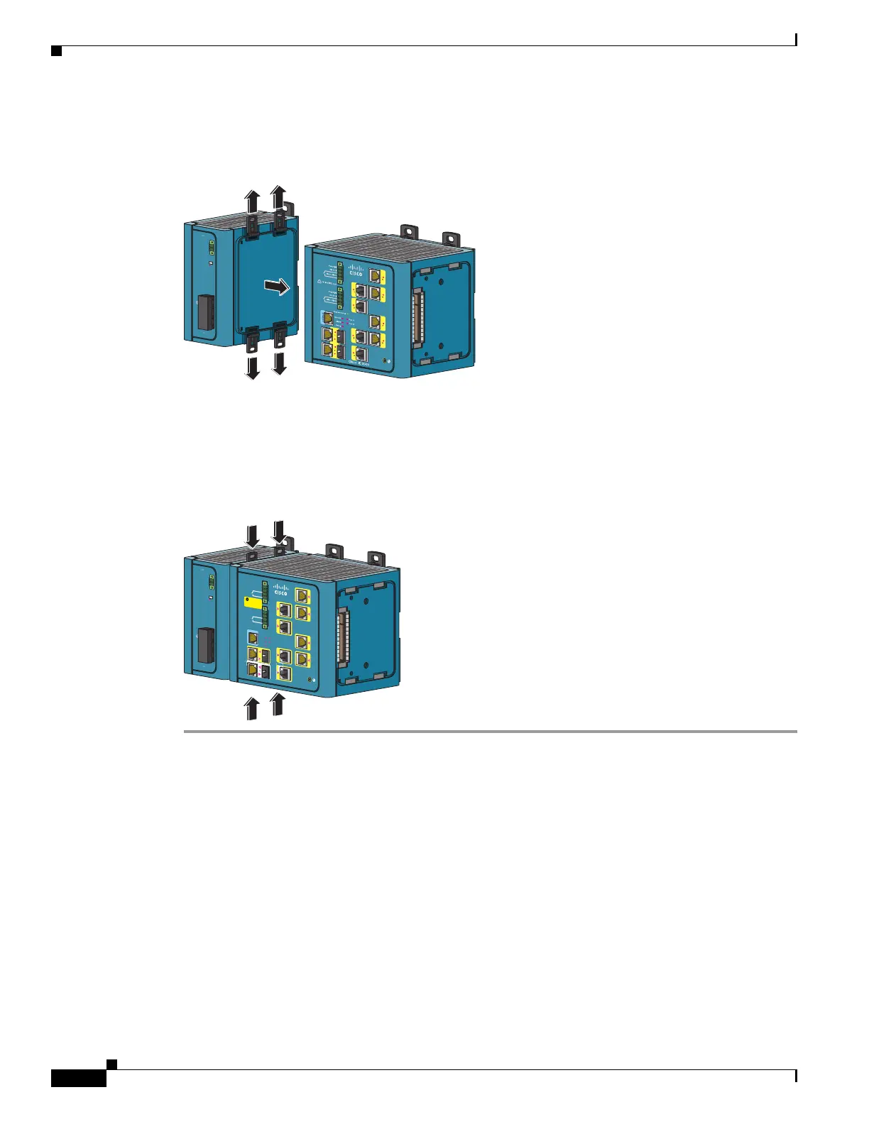
Connecting the Switch to the Power Converter
Step 2 Push the upper modules latches (at the top of the switch and the power converter) up and the lower
module latches (at the bottom of the switch and the power converter) down. See Figure B-39.
Figure B-39 Pushing the Module Latches Up and Positioning the Hardware
Step 3
Put the two modules together so that the power module fits in the switch recess.
Step 4 Push the upper module latches down and the lower module latches up to secure the power converter to
the switch. See Figure B-40.
Figure B-40 Pushing the Latches In
D
C
O
K
2
4
V
, 2.1A
R
tn
O
u
t
(-)
P
w
r
Ou
t
(+
)
1
2
5
-25
0
V
,
1
.
2
5
A
M
A
X
1
00
-
2
4
0
V
~,
5
0
-6
0
H
z
/
N
/
L
/
202296
D
C
OK
2
4
V
,
2
.
1
A
R
t
n
Ou
t
(
-
)
P
w
r
O
u
t
(
+
)
125
-
25
0
V
,
1
.2
5
A
M
AX
10
0
-
24
0
V
~
,
5
0
-
60
H
z
/
N
/
L
/
Ci
sc
o
C
at
aly
st
Pw
r
A
(
2
4VD
C o
r
48
VDC
)
Rt
n
A
Pw
r
B
(
24
VD
C
o
r
4
8
VD
C
)
Rt
n
B
Ex
pre
s
s
S
e
t
u
p
S
y
s
t
e
m
A
l
ar
m
S
e
t
up
P
w
r
A
Pw
r
B
Ma
j
o
r
A
la
r
m
M
i
n
o
r
A
l
a
r
m
T
h
i
s
u
n
i
t
m
i
ght
h
a
ve
m
o
r
e
t
h
an
o
n
e
p
o
we
r
co
r
d
.
To
redu
c
e
t
h
e
r
i
s
k
of
e
l
e
c
t
ri
c
s
ho
ck
d
is
c
o
nn
e
ct
t
h
e
t
w
o
p
o
w
e
r
c
o
r
d
s
b
e
f
o
r
e
s
e
r
v
ic
in
g
u
n
it.
WA
R
N
I
N
G
!
202297
1
5
2
6
3
7
4
8
CONSOLE
1
2