2-53
Cisco IE 3000 Switch Hardware Installation Guide
Chapter 2 Switch Installation
Connecting the Switch to the Power Converter
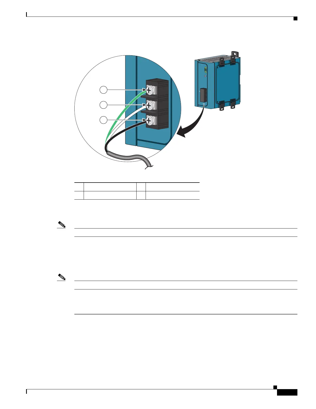
Figure 2-43 Connecting AC Power to the Power Converter
Step 3 Tighten the ground wire terminal block screw.
Note The torque should not exceed 2.2 in-lb (0.25 Nm).
Step 4 Insert the line and neutral wire leads into the terminal block line and neutral connections. See
Figure 2-43. Make sure that you cannot see any wire lead. Ensure that only wire with insulation extends
from the connectors.
Step 5 Tighten the line and neutral terminal block screws.
Note The torque should not exceed 2.2 in-lb (0.25 Nm).
Step 6 Replace the plastic cover over the terminal block.
Step 7 Connect the other end of the AC power cord to the AC outlet.
1 Ground 3 AC line
2 AC neutral
D
C
O
K
24
V
, 2.1A
Rtn Out
(-
)
P
w
r
O
ut
(+)
1
2
5
-
2
5
0
V
,
1
.2
5
A
M
AX
1
0
0-
2
4
0
V
~
,
5
0
-
6
0
H
z/
N
/
L
/
202300
3
2
1