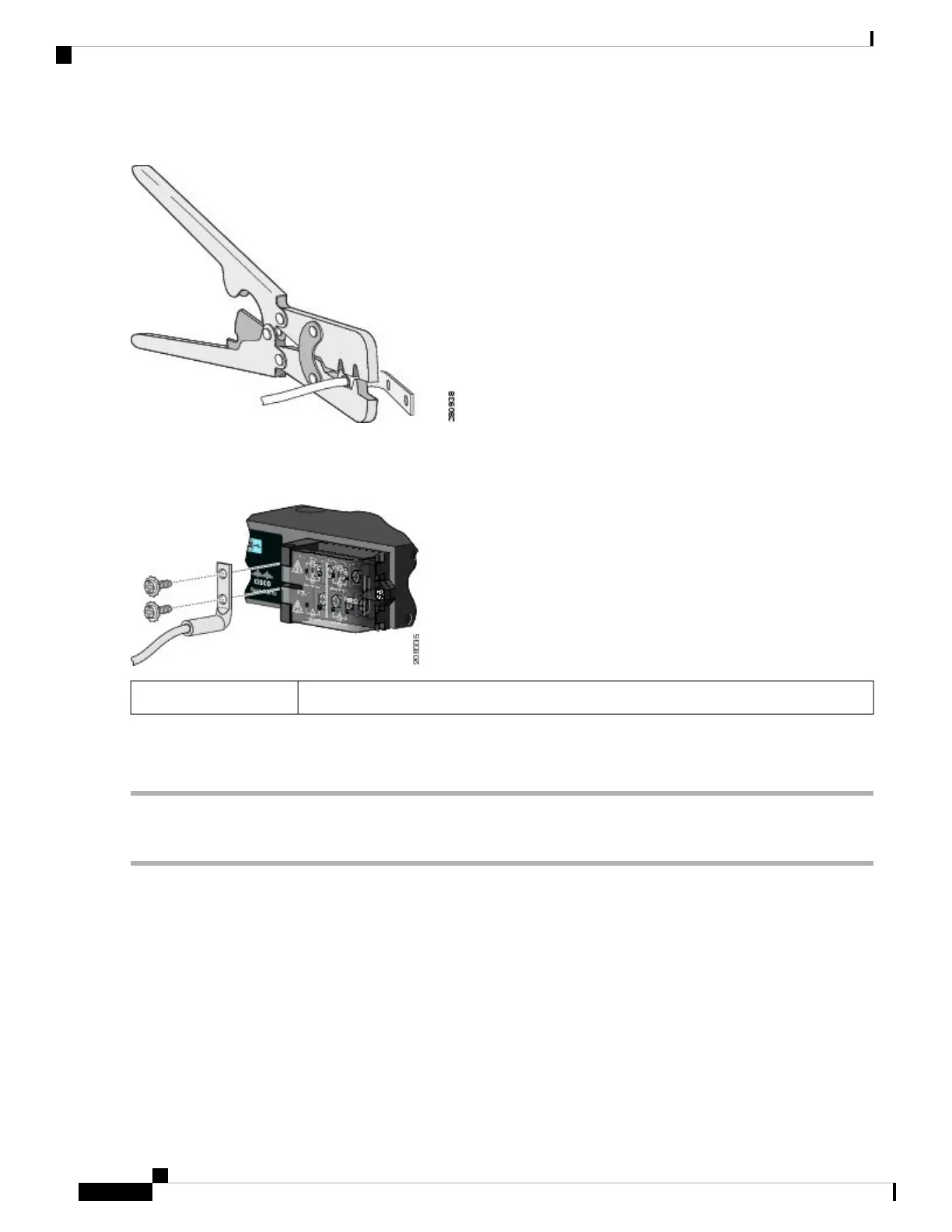
Figure 22: Crimping the Terminal Lug
Step 4 Slide the ground screw from Step 1 through the terminal lug. Insert the ground screws into the opening on the cable side.
Figure 23: Attaching the Terminal Lug
Dual-hole terminal lug1
Step 5 Use a ratcheting torque screwdriver to tighten the ground screws to 30 in-lb (± 2 in-lb).
Step 6 Attach the other end of the ground wire to an appropriate ground.
Installing the Power-Supply Module in the Switch
Step 1 Ensure that the power is off at the AC or DC circuits.
Locate the circuit breakers, turn them OFF, and lock out the circuit.
If the power is not off at the AC or DC circuit breaker, do not touch the power-input terminal.
Warning
Step 2 Use a Phillips screwdriver to loosen the two captive screws of the blank power-supply module and gently pull it out. See
the following figures.
Cisco IE 4010 Switch Hardware Installation Guide
42
Power Supply Installation
Installing the Power-Supply Module in the Switch
 Loading...


