Figure 26: Crimping the Spade Terminal Lug
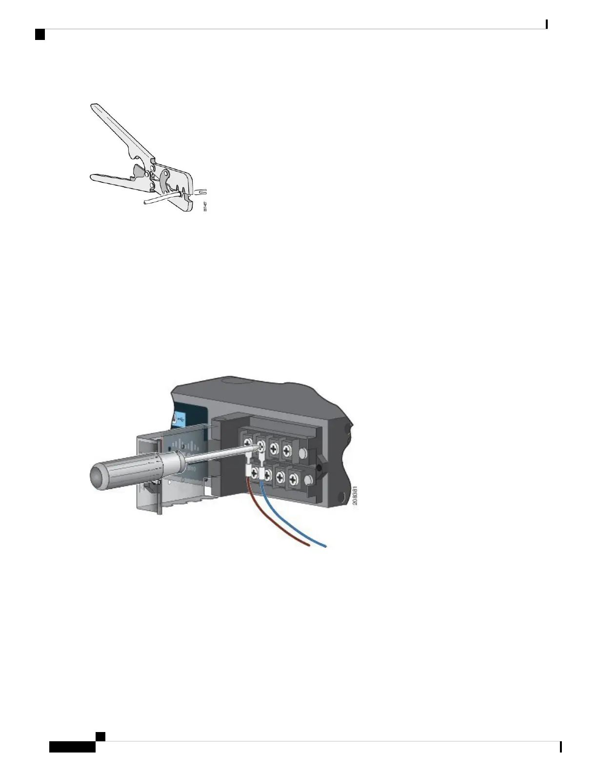
Step 6 Loosen the terminal screw, and slide the terminal under the screw and washer. See Figure 28: Connecting the Wires
to the Low-Voltage DC Power (PSU2), on page 43.
Use the appropriate terminal screws based on power supply type: high-voltage (AC or DC) or low-voltage
(DC).
Note
Step 7 Make the power connection:
AC Power Connection
• Connect the line wire into the terminal screw labeled L and the neutral wire into the terminal screw labeled N to
complete the AC connection.
Figure 27: Connecting the Wires to the High-Voltage AC Power (PSU1)
DC Power Connection
• Connect the positive wire into the terminal screw labeled “+” , and the negative wire into the terminal screw
labeled “– ”.
Low-voltage DC Power-Supply Module
• Connect the wires to the terminals labeled Lo.
High-voltage DC Power-Supply Module
• Connect the wires to the terminals labeled Hi.
Cisco Catalyst IR8340 Rugged Series Router Hardware Installation Guide
42
Power Supply Installation
Wiring the Power Source
 Loading...