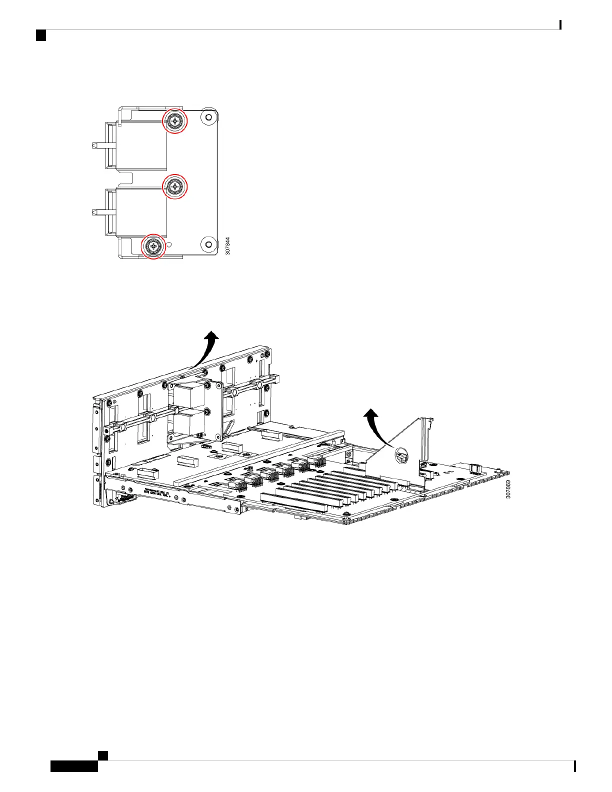
Figure 59: Location of Bridge Card Screws
Step 9 Grasp the Midplane assembly handle and the Midplane frame and lift the entire midplane assembly out of the chassis.
The following illustration shows where to grasp the Midplane Assembly.
Figure 60: Location of Hand Holds for Removing the Midplane Assembly (Horizontal View)
Step 10 Remove the rear sub assembly.
a) Using a screwdriver, rotate each of the screws counter clockwise until it disengages from the midplane frame.
b) Grasp the rear sub assembly and disconnect it from the Midplane frame.
c) Grasp the PCIE module and separate it from the Midplane frame.
The following illustration shows the location of the screws.
The following image is straight on showing the rear of the midplane assembly.
Note
Maintaining the Server
108
Maintaining the Server
Recycling the PCB Assembly (PCBA)

 Loading...