1-4
Cisco VG202 and Cisco VG204 Voice Gateways Hardware Installation Guide
OL-15959-01
Chapter 1 Overview of the Cisco VG202 and Cisco VG204 Voice Gateways
Physical Description
LEDs
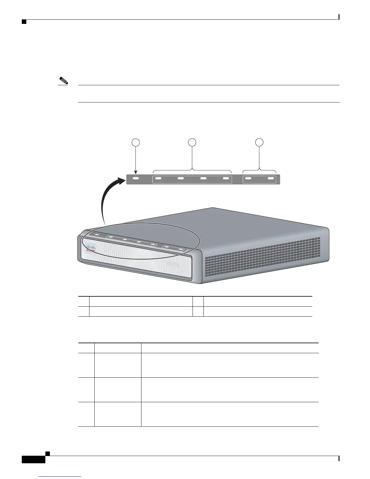
Figure 1-5 shows the LEDs on the Cisco VG204 voice gateway. All LEDs are on the front of the chassis.
Note LEDs on the Cisco VG202 and Cisco VG204 are the same; however, the Cisco VG202 has LEDs for
only two FXS ports.
Table 1-1 describes the status of each LED on the Cisco VG202 and Cisco VG204.
Figure 1-5 Cisco VG204 Voice Gateway LEDs
1 OK LED 2 FXS0, FXS1, FXS2, FXS3 LEDs
3 Fast Ethernet 0/0 and 0/1 LEDs
Ta b l e 1-1 Cisco VG202 and Cisco VG204 LEDs
No LED/Color Description
1 PWR
OK—green
Off—no power
Steady on—normal operation
Slow blink—bootup phase or in ROMMON monitor mode
2 FXS ports 0
through
3—green
Off—On hook
Steady On—Off hook
3 FE ports
0/1—green
Off—No link
Steady on—link
Blinking—TXD/RXD data
V
G204
O
K
F
X
S
0
/
0
0/
1
0
/
2
F
E
0
/
0
0
/
1
0
/
3
272226
OK 0/0 0/00/1 0/10/2 0/3
FXS FE
2
3
1

 Loading...


