1-3
Cisco VG248 Analog Phone Gateway Hardware Installation Guide
78-13154-01
Chapter 1 Overview
Front Panel
Front Panel
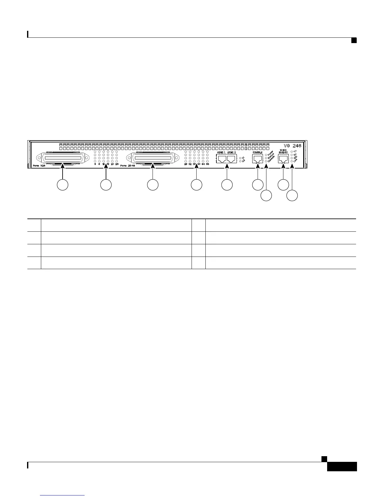
Figure 1-2 provides an overview of the interfaces and LED displays on the front
panel of the VG248.
Figure 1-2 VG248 Front Panel
FXS Telco Connectors
The FXS interface consists of two telco (RJ-21) connectors featuring these
characteristics:
• On-premise connections only—analog phones must be physically located in
the same building as the VG248.
• Maximum supported line length—5000 feet or 415 Ohms.
• Loop start support
• Support for disconnect supervision
• DTMF dialing
• Maximum ringer equivalency number (REN) load—3 per line, and only two
phones per line can be off-hook at any one time
1 FXS telco connectors, ports 1-24 and 25-48 5 System status indicators
2 Port status indicators, ports 1-24 and 25-48 6 Ethernet port
3 Async 1 and 2 ports, unused 7 Ethernet status indicators
4 Console port
1 2 1 2 3 4
5
6
7
58952

 Loading...


