Chapter 1 Overview
Front Panel
1-6
Cisco VG248 Analog Phone Gateway Hardware Installation Guide
78-13154-01
Status Indicators
Three sets of status indicator LEDs on the front panel display the VG248 status:
• Port Status Indicators
• System Status Indicators
• Ethernet Status Indicators
Table 1-3 includes descriptions of the LED states of these status indicators.
21, 46 Port 45 transmit/receive
22, 47 Port 46 transmit/receive
23, 48 Port 47 transmit/receive
24, 49 Port 48 transmit/receive
25, 50 Unused
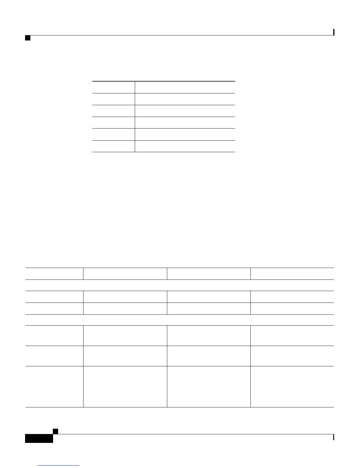
Table 1-2 FXS Ports 25-48 Connector Pinouts (continued)
Pin Number Function
Table 1-3 LED Status Explanation
LED On Flashing Off
Port Status Indicators
Ports 1-24 Off hook Ringing Not connected or on hook
Ports 25-48 Off hook Ringing Not connected or on hook
System Status Indicators
Power Power connected and
operating normally
N/A Power not connected
Console Console link connected N/A Console link not
connected
Status Operating normally Potential hardware error
detected.
Check the event log for
details.
Not operating normally

 Loading...


