1-7
Cisco VG248 Analog Phone Gateway Hardware Installation Guide
78-13154-01
Chapter 1 Overview
Front Panel
Console Port
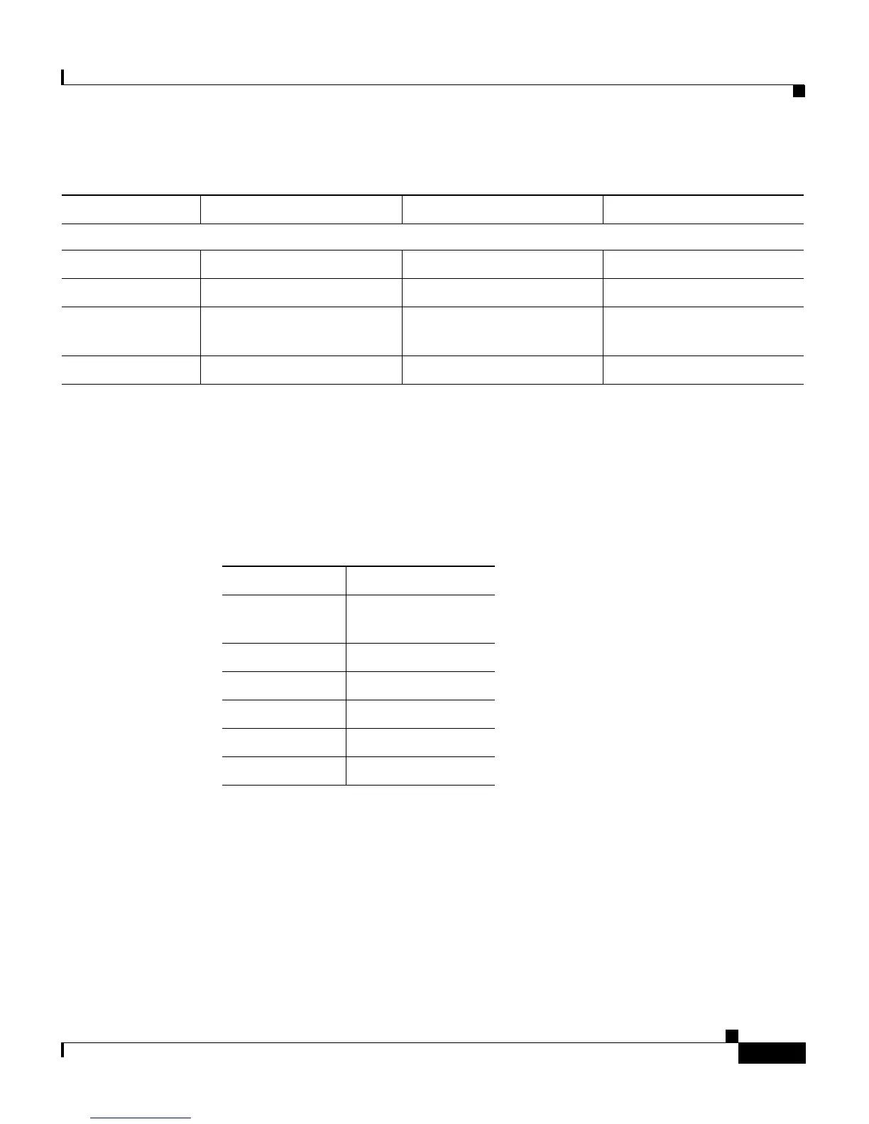
Use the console port to connect the VG248 to a console terminal for configuration
and management tasks. Table 1-4 describes the console port connector pinouts.
Ethernet Port
Use the Ethernet port to connect the VG 248 to the IP network to access
Cisco CallManager. Table 1-5 describes the Ethernet port connector pinouts.
Ethernet Status Indicators
TX N/A Packet transmitted. Nothing transmitted
RX N/A Packet received. Nothing received
100 Connected at 100 Mbps N/A Connected at 10 Mbps or
not connected
Link Ethernet link connected N/A Not connected
Table 1-3 LED Status Explanation (continued)
LED On Flashing Off
Table 1-4 Console Port Connector Pinouts
Pin Number Function
1, 8 Connected to each
other
2DTR
3TxD
4,5 Ground
6RxD
7DSR

 Loading...


