1-4
Catalyst 3560 Switch Hardware Installation Guide
OL-6337-07
Chapter 1 Product Overview
Front Panel Description
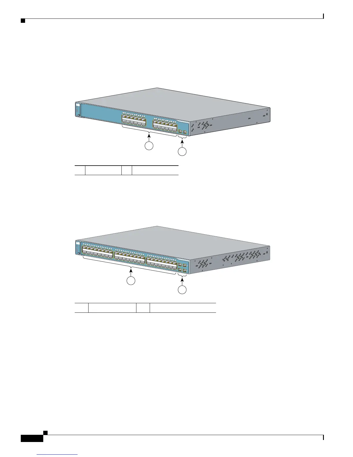
The 10/100 ports on the switch are grouped in pairs. The first member of the pair (port 1) is above the
second member (port 2) on the left, as shown in Figure 1-2. Port 3 is above port 4, and so on. The SFP
module slots are numbered 1 and 2.
Figure 1-2 Catalyst 3560-24TS-S, 3560V2-24TS, and 3560V2-24TS-SD Switch Front Panel
The 10/100 PoE ports on the switch are grouped in pairs. The first member of the pair (port 1) is above
the second member (port 2) on the left, as shown in Figure 1-3. Port 3 is above port 4, and so on. The
SFP module slots are numbered 1 to 4.
Figure 1-3 Catalyst 3560-48PS and 3560V2-48PS Switch Front Panel
1 10/100 ports 2 SFP module slots
126808
2
C
atalyst 35
60
S
E
R
I
E
S
M
O
D
E
1
1
2
3
4
5
6
7
8
9
1
0
1
1
1
2
1
4
1
5
1
6
1
7
1
8
1
9
2
0
2
1
2
2
2
3
2
4
1
3
1X
2X
11X
12X
13X
14X
23X
24X
RP
S
S
T
A
T
D
U
P
L
X
S
P
E
E
D
S
YS
T
1
2
1 10/100 PoE ports 2 SFP module slots
97911
2
1
C
atalyst 356
0
S
E
R
IE
S
PoE-48
SY
S
T
R
P
S
S
TA
T
D
U
P
L
X
S
P
E
E
D
P
oE
M
O
D
E
1
2
5
6
7
8
9
1
0
1
1
1
2
1
3
1
4
1
5
1
6
3
4
1
X
2
X
1
5
X
1
6
X
1
7
1
8
2
1
2
2
2
3
2
4
2
5
2
6
2
7
2
8
2
9
3
0
3
1
3
2
1
9
2
0
1
7
X
1
8
X
3
1
X
3
2
X
3
3
3
4
3
7
3
8
3
9
4
0
4
1
4
2
4
3
4
4
4
5
4
6
4
7
4
8
3
5
3
6
3
3
X
3
4
X
4
7
X
4
8
X
1
2
3
4

 Loading...


