1-6
Catalyst 3560 Switch Hardware Installation Guide
OL-6337-07
Chapter 1 Product Overview
Front Panel Description
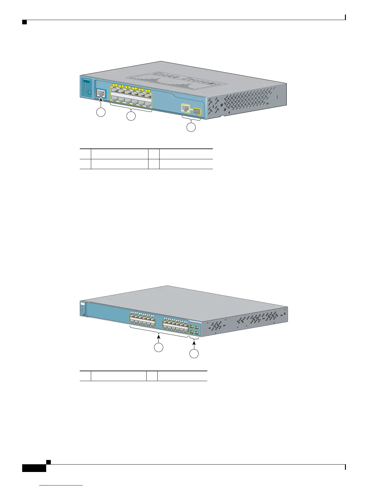
Figure 1-6 Catalyst 3560-12PC-S Switch Front Panel
Gigabit Ethernet Switch Front Panel Descriptions
• Catalyst 3560G-24PS Switch Front Panel, Figure 1-7 on page 1-6
• Catalyst 3560G-24TS Switch Front Panel, Figure 1-8 on page 1-7
• Catalyst 3560G-48PS Switch Front Panel, Figure 1-9 on page 1-7
• Catalyst 3560G-48TS Switch Front Panel, Figure 1-10 on page 1-8
The 10/100/1000 PoE ports on the Catalyst 3560G-24PS switch are grouped in pairs. The first member
of the pair (port 1) is above the second member (port 2) on the left, as shown in Figure 1-7. Port 3 is
above port 4, and so on. The SFP module slots are numbered 25 to 28.
Figure 1-7 Catalyst 3560G-24PS Switch Front Panel
1 Console port 3 Dual-purpose port
2 10/100 PoE ports
2
3
1
CON
SOLE
Catalyst 3560
SERIES
PoE-12
PoE
SPD
DPLX
STAT
SYST
MODE
1
1
2
3
4
6
7
8
9
10
11
1
2
5
250606
1 10/100/1000 ports 2 SFP module slots
119676
2
Catalyst 3560G
S
E
RIES
PoE-24
M
O
D
E
1
1
2
3
4
5
6
7
8
9
1
0
1
1
1
2
1
4
1
5
1
6
1
7
1
8
1
9
2
0
2
1
2
2
2
3
2
4
1
3
1X
2X
11X
12X
13X
14X
23X
24X
R
P
S
S
T
A
T
D
U
P
L
X
S
P
E
E
D
P
o
E
S
Y
S
T
25
26
27
28
 Loading...


