2-13
Catalyst 3560 Switch Hardware Installation Guide
OL-6337-07
Chapter 2 Switch Installation (24- and 48-Port Switches)
Installing the Switch
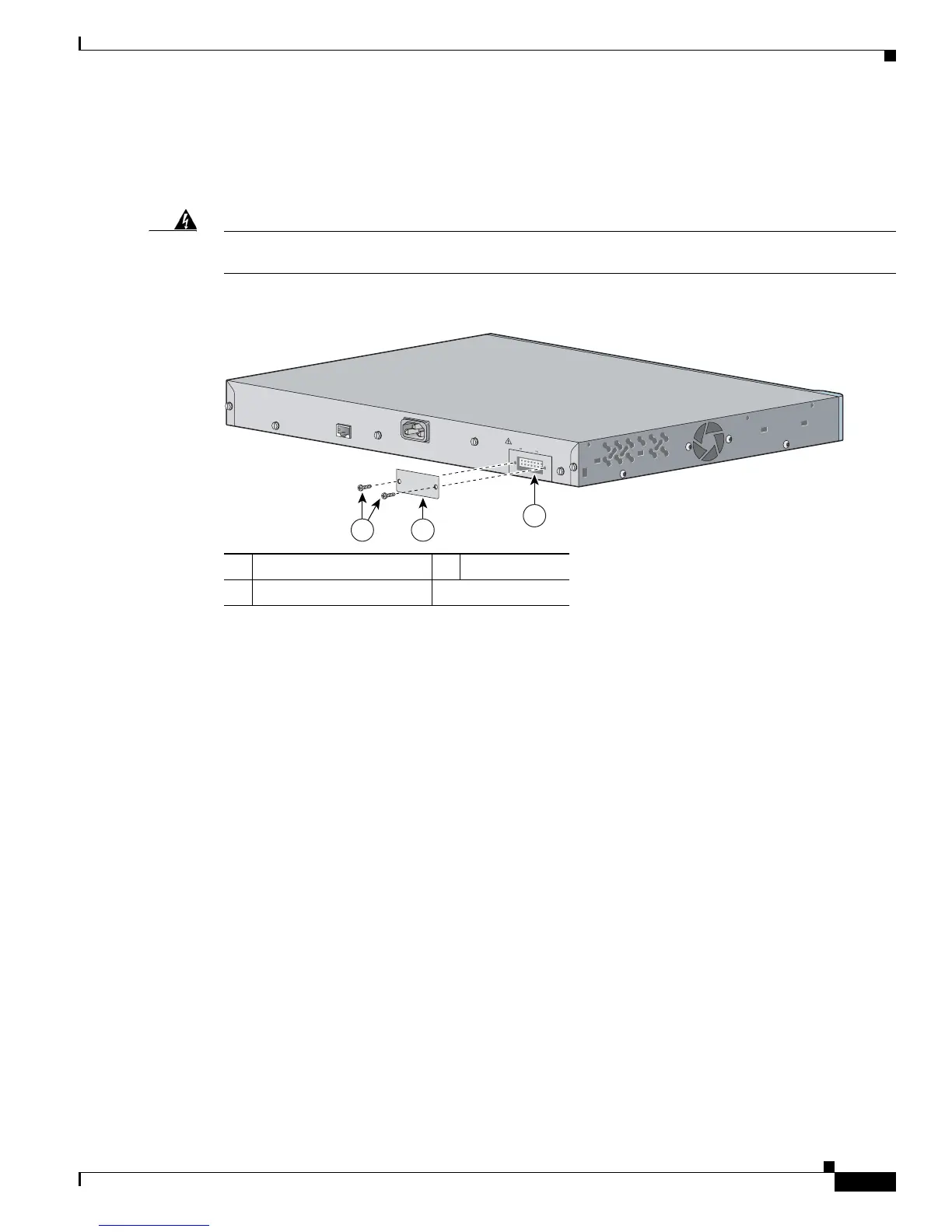
Attaching the RPS Connector Cover
If you are not using an RPS with your switch, use the two Phillips pan-head screws to attach the
RPS connector cover to the back of the switch, as shown in Figure 2-11.
Warning
If a redundant power system (RPS) is not connected to the switch, install an RPS connector cover on
the back of the switch.
Statement 265
Figure 2-11 Attaching the RPS Connector Cover on the Catalyst 3560 Switch
1 Phillips pan-head screws 3 RPS connector
2 RPS connector cover
97926
RATING
100-200V ~
5.0A-2.5A, 50-60 HZ
CO
N
SO
LE
DC INPUTS FOR REMOTE
POWER SUPPLY
SPECIFIED IN MANUAL
+12v @
7.5A -48 @7.8A
2
3
1
 Loading...


