3-5. Disassembly, Reassembly and Lubrication
CLP-621 & CLP-631 3-28
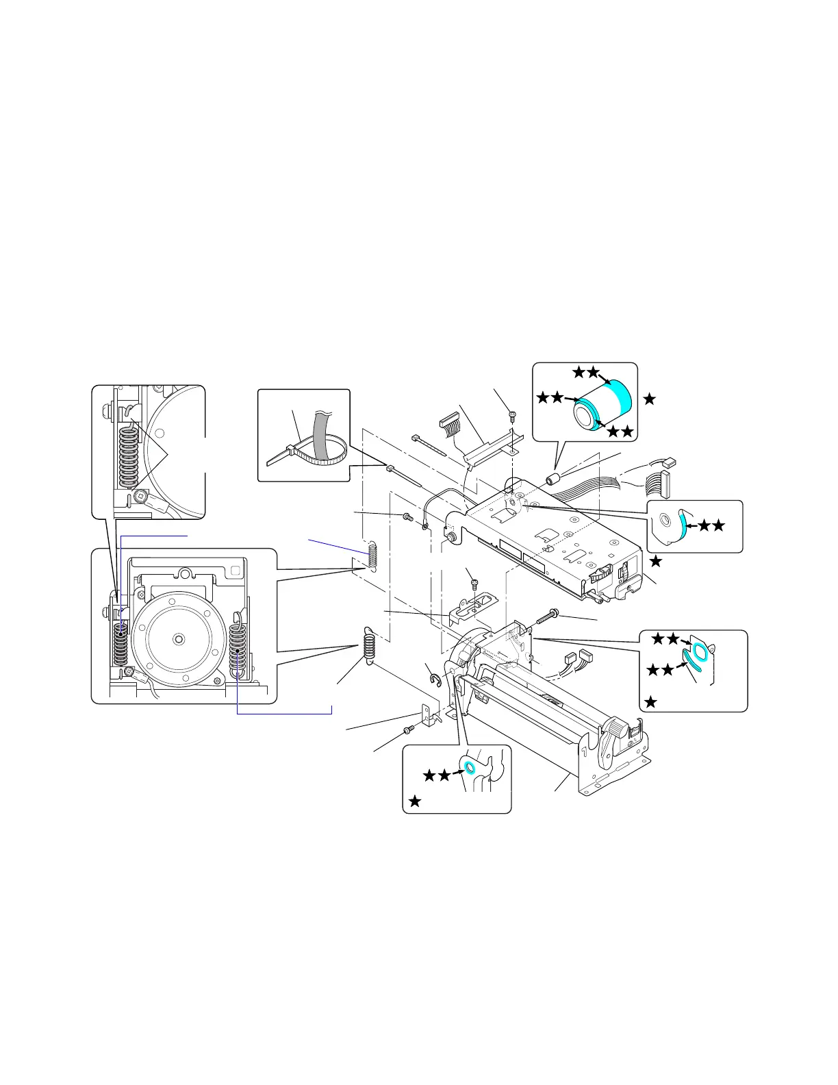
3-5-17. Head Block and PF Unit
1. Remove the Mechanism Unit. Refer to 3-5-13 “Mechanism Unit and Case L”.
2. Remove 1 screw (BH (N), M3x3) to detach the Cable Guide Plate (1) from the Head Block.
3. Remove 1 screw (PH, M3x6) (2) to detach the earth lug from the frame.
4. Open the Head Block and disengage the Head Up Spring (3) and the Head Up Spring 2 (4)
from the Mechanism Unit.
Note: Hold the Head Block as it can fall when the springs are removed.
5. Remove 1 screw (PH (SW+PW), M4x16) and the Head Holder Shaft (5).
6. Disengage 1 E-ring and detach the Head Block (6) from the PF Unit Block.
7. Remove 1 screw (BH (N), M3x6) and remove the Motor Cover Bracket (7) from the PF Unit
Block.
8. Remove 1 screw (BH (N), M3x6) and remove the Head Up Spring 2 Hook (8) from the PF Unit
Block.
Lower side Wire Tie
(Flat side)
5Shaft, Head Holder
(
6Head Block)
3Spring, Head Up
4Spring2, Head Up
Unit, PF
PH (SW+PW), M4x16
2PH, M3x6
E-Ring, 4
7Bracket, Motor
Cover
8Hook, Head Up Spring 2
BH (N), M3x6
Open ends of
the spring
BH (N), M3x3
FLOIL G-311S
FLOIL G-311S
FLOIL G-311S
1Plate, Cable Guide
BH (N), M3x6
FLOIL G-311S
A
B
C
D
Notes on reassembling:
• When assembling, apply G-311S to the following places shown by the
mark.
A: Hole (front left). Circumference surface of the hole (on both sides) and inside the hole
B: Hole and protrusion (rear left). Circumference surface of the hole (on both sides) and along
the protrusion surface.
C: Along the contacting surface (rear left).
D: 3 surfaces on the Head Holder Shaft.
• When assembling the Head Holder Shaft, be sure that its assembling direction is correct.