2-2. Operation of Control Parts
2-25 CLP-621 & CLP-631
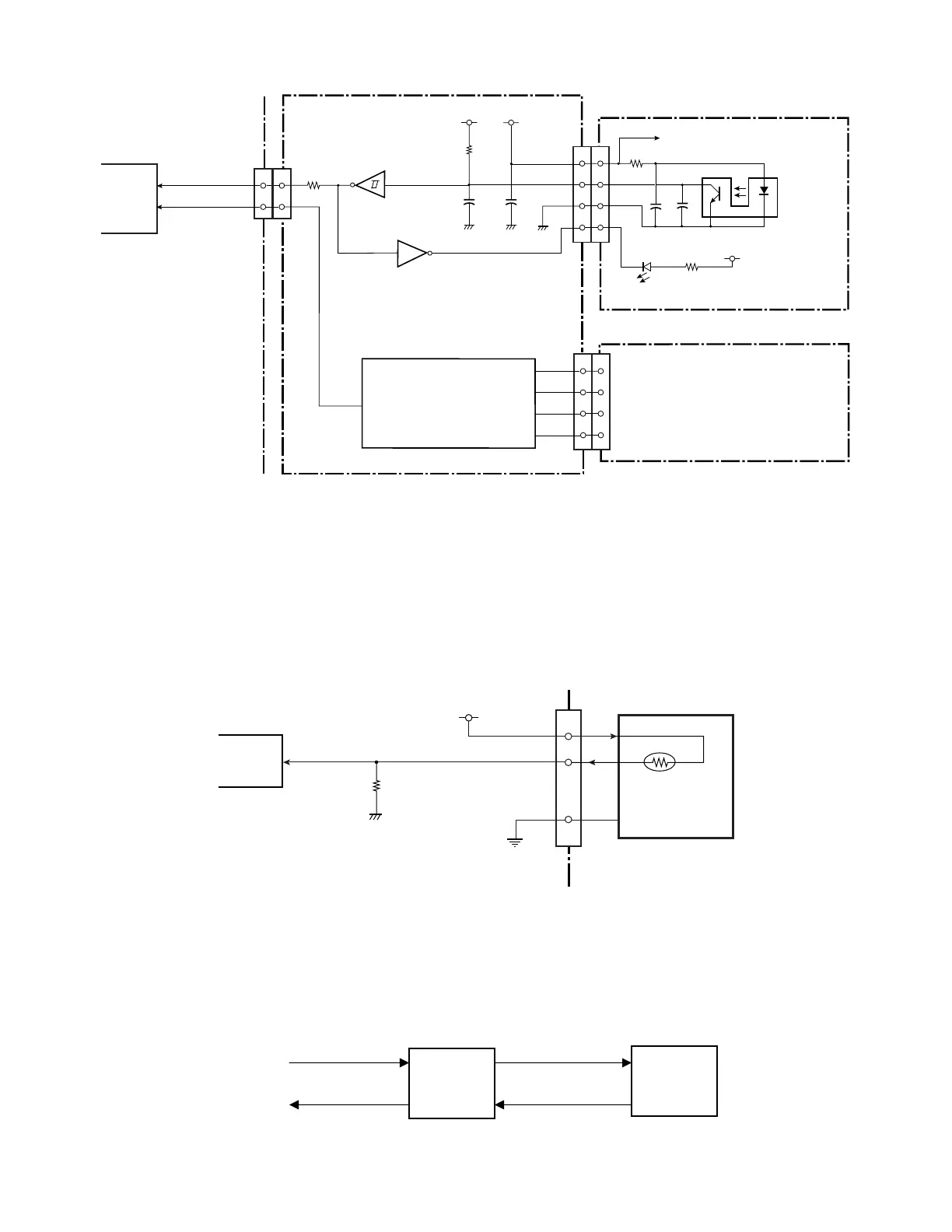
[Tension Sensor PCB]
Tension Sensor
2
3
1
CN901
PI901
R901
C902
C901
+3.3V
4
+3.3V
R902
D901
Take-up side
[Tension Sensor PCB]
2
3
1
4
Supply side
2
3
1
CN704
4
(Same as above circuit)
CN901
2
3
1
CN705
4
[Ribbon Main PCB]
+3.3V
R727
+3.3V
C719
C720
2
4
IC708A
18
17
CN701
IC707A
6
7
(Same as above circuit)
IC11
Custom IC
SENS_A
97
PM2
10
9
SENS_B
98
PM3
[Main PCB]
CN8
R728
(3-4) Head temperature sensor
The head temperature sensor is used to detect the temperature of the thermal head. This
sensor is a thermistor incorporated in the Head SA. Since the resistance of the thermistor
changes according to the temperature change, the voltage at pin 7 (HDTMP) of IC1 (CPU)
changes accordingly. The CPU senses the voltage at pin 7 to detect the head temperature.
According to the temperature of the print head, the CPU controls the printing pulse width
applied to the thermal elements to keep the printing density constant.
CN4
Thermal Head
5,6,8,11,12,20,22
HDTHM2
+3.3V
19
R85
HDTMP
IC1
CPU
ANI2
7
Head Temp.
Thermistor
[Main PCB]
21
HDTHM1
Printing operation at the head temperature rise:
When the head temperature reaches 65
°C (149°F), printing stops after printing the current
label. In this case, PRINT LED and CONDITION LED simultaneously blink on the
operation panel. When the temperature of the Head SA falls below 55
°C (131°F), LEDs
stop blinking and printing resumes.
55°C
(131
°F)
65°C
(149
°F)
Normal speed
(Stop)
Normal speed
Normal speed
(Stops)