2-2. Operation of Control Parts
CLP-621 & CLP-631 2-32
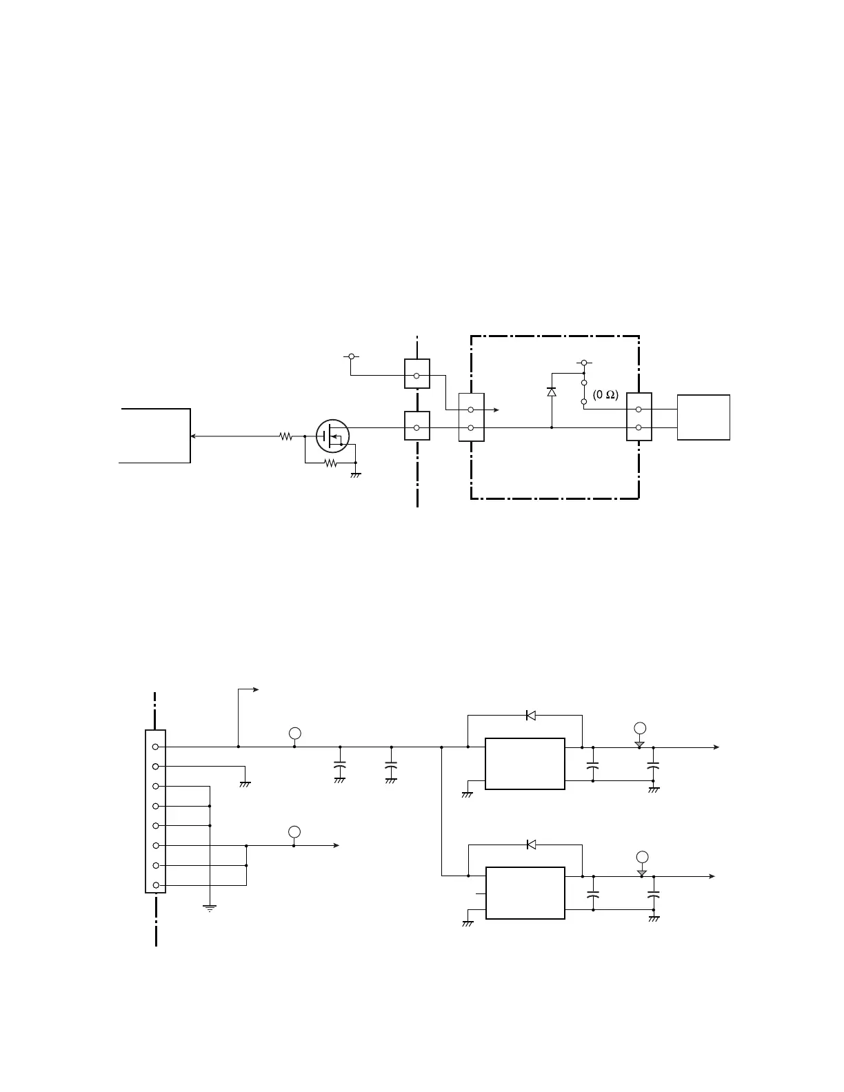
(4-5) Fan driver
This circuit drives the ribbon motor cooling fan.
When pin 130 (FANCTL) is set to “Low” level, TR5 turns ON and the fan is driven.
The fan is driven according to the Ribbon Motor F temperature detected by the ribbon
motor temperature sensor.
When the temperature is under 45
°C (113°F), the fan is not driven.
When the temperature exceeds 45
°C (113°F) during ribbon motor running, the fan starts to
turn.
If the temperature is 70
°C (158°F) or more after the ribbon motor is stopped, the fan is kept
turned until the temperature falls under 70
°C (158°F).
130
FANCTL
IC1
CPU
D30
1
R130
R131
TR5
2SK3577
[Main PCB]
CN8
11
1
CN21
D701
+5V
+5V
19
+5V
FANOUT
1
2
F702
Fan
CN706
Ribbon Motor Fan
CN701
[Ribbon Main PCB]
(5) Other circuits
(5-1) +3.3V/+1.5V circuit
The Main PCB receives +5V and +24V from the Power Supply Unit. +5V and +24V are
used for control circuits and driver circuits, respectively.
IC15 and IC16 are the regulator ICs to produce +3.3V and +1.5V from +5V.
+3.3V is used for various logic circuits. +1.5V is supplied to the CPU (IC1) only.
3
4
1
4
5
2
CN10
6
7
8
+24V
T18
+24V
+5V
+5V
T16
D9
EC2
P222
+3.3V
C78
IC15
uPC2933AT
Vin
1
Vout
3
GND
42
GND
Vin
Vout
P223
IC16
XC6209F152PR
D10
C79
C80
4
5
VSS
2
NC
1
CE
3
+
+3.3V
T17
+1.5V
+1.5V
T19
[Main PCB]
+3.3V Regulator
+1.5V Regulator
EC1
C81
+
From
Power
Supply
Unit